Spread spectrum signal

a spectrum signal and signal technology, applied in the field of signal modulation, can solve the problems of reducing positioning accuracy, affecting overall tracking performance, time-varying amplitude components of modulation, etc., and achieves the effect of high spectral control and good overall synchronisation capabilities

Active Publication Date: 2012-05-29
CENT NAT DETUD SPATIALES C N E S
View PDF4 Cites 21 Cited by
  • Summary
  • Abstract
  • Description
  • Claims
  • Application Information

AI Technical Summary

Benefits of technology

[0008]The invention provides a spread-spectrum signal, which combines a high level of spectral control with good overall synchronisation capabilities.
[0014]Compared with a conventional BOC waveform at the first waveform rate, the present spreading waveform has improved tracking capabilities due to the presence of the second waveform at a higher waveform rate. The spectrum of the spreading waveform depends on the respective spectra of the first and the second waveform. By varying the relative amplitudes of the first and the second waveform, one can adjust the shape of the spreading waveform spectrum. With regard to prior approaches of spectral shaping, the present signal has the additional advantage that different lobes in the spectrum of the spreading waveform can be accessed individually. This insures spectral isolation to other signals in the same frequency band while maintaining tracking performances. When compared to a BOC-modulated signal the tracking performances are even enhanced. It will be appreciated that the relative amplitudes of the first and the second waveform may themselves vary in time or remain constant. The timescale of this variation is much larger than the timescale of signal oscillations. Preferably, such variations occur at a rate substantially lower than the rate of the binary sequence, e.g. 1 Hz. On the short time-scale, the time-dependency of the coefficients in the linear combination can thus be neglected.
[0034]The method allows shaping of the signal spectrum so as to respect certain thresholds of spectral isolation (for example a certain spectral separation coefficient (SSC) to another signal), while increasing its synchronisation capabilities.

Problems solved by technology

The question of spectral isolation is e.g. an important issue with regard to the interoperability of the Galileo satellite system and the existing Global Positioning System.
It is well known in the field of radionavigation that filtering or reducing the secondary lobes of a signal also degrades the synchronisation capabilities (or tracking performances) of this signal, which reduces the positioning accuracy.
Although approximating a sinusoidal waveform provides an efficient and elegant way of improving spectral isolation of some signals (for example the GPS M-Code when applied to a BOC(2,2) signal), it does so to the disadvantage of overall tracking performances.
A further challenge in signal modulation techniques is elimination of time-varying amplitude components of the modulation.
Amplitude variations give rise to undesired AM-to-AM and AM-to-PM distortions when the signal is processed by nonlinear components (e.g. amplifiers).

Method used


Image

  • Spread spectrum signal
  • Spread spectrum signal
  • Spread spectrum signal

Examples


Embodiment Construction

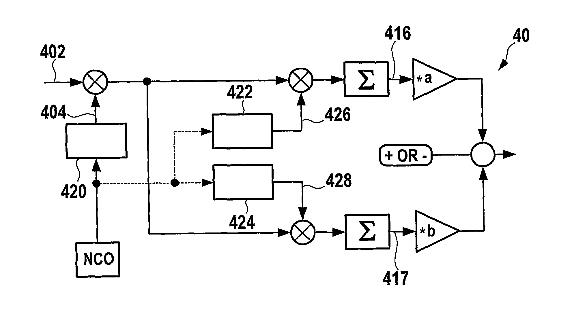
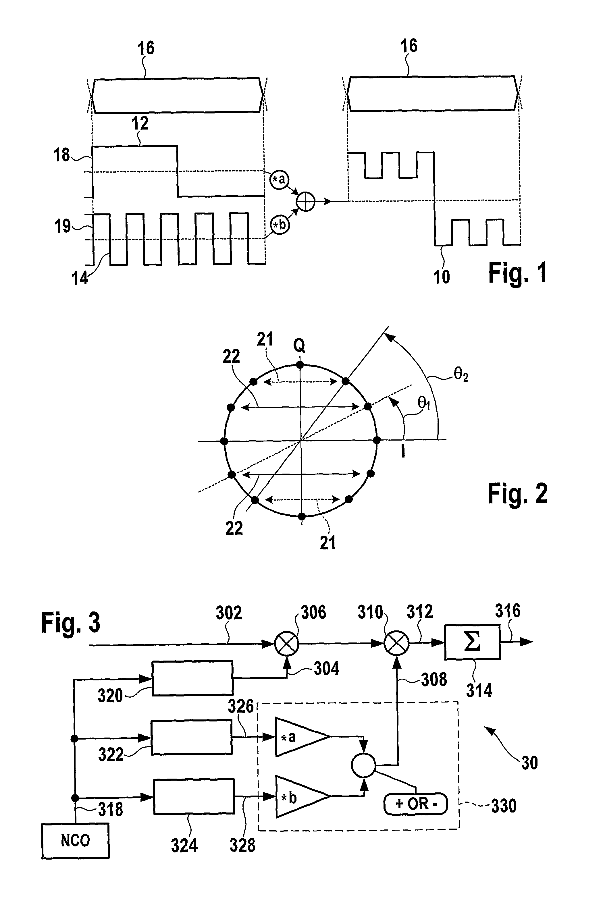
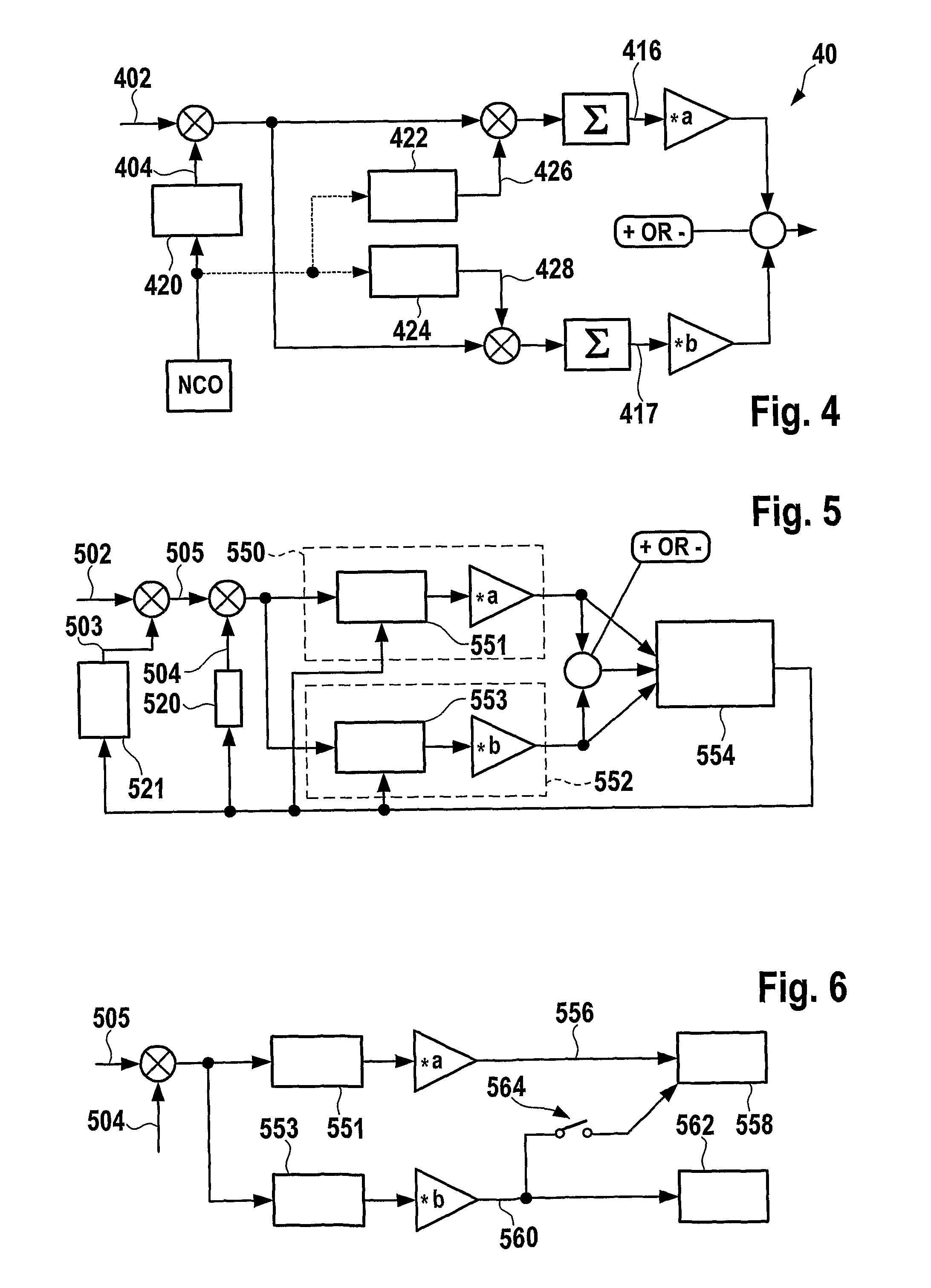
[0060]Referring to FIG. 1, an example of a spreading waveform 10 for modulating a carrier wave is discussed in more detail. In this embodiment, the spreading waveform 10 is obtained by coherently summing a first binary waveform 12 formed by a BOC(m1, n) multiplied by a first coefficient a, and a second binary waveform 14 formed by a BOC(m2, n) multiplied by a second coefficient b. The BOC(m2, n) waveform could advantageously be replaced by a more general binary waveform, like a BCS e.g. a BCS([1-1 1 1 1 1 1 1 1 1], 1]). As seen in FIG. 1, the spreading waveform 10 has a crenellated shape. The same code 16 is applied to both waveforms. In other words, the first waveform 12 and the second waveform 14 are modulated with a single binary code sequence 16 according to the formula:

s(t)=(a·w1(t)+b·w2(t))·PRN(t).

[0061]This is also written as:

s(t)=a·w1(t)·PRN(t)+b·w2(t)·PRN(t),

[0062]where t represents a time variable, s(t) is the resulting spreading waveform 10, w1(t) is the first binary wave...


PUM


Abstract

A spread-spectrum signal comprises a spreading waveform modulating a carrier wave and containing a real linear combination of a first waveform at a first waveform rate and a second waveform at a second waveform rate, the first waveform rate being distinct from the second waveform rate and both waveform rates being distinct and non-zero. The linear combination of the first and the second waveform is modulated with at least one binary sequence comprising a signal identification code.

Description

TECHNICAL FIELD OF THE INVENTION[0001]The present invention generally relates to the field of signal modulation, in particular with regard to satellite navigation systems. The invention further concerns a method for producing a spread-spectrum signal and appropriate techniques for receiving such a spread-spectrum signal, in particular with regard to satellite navigation systems.BRIEF DESCRIPTION OF RELATED ART[0002]The use of spread-spectrum techniques for radionavigation or communication is well known in electrical engineering. This technology is e.g. advantageous in applications requiring high reliability in noisy environment. Furthermore, due to the limited availability of spectrum allocations, efficient use of frequency bands has become desirable.[0003]The implementation of new signals in a given frequency band must satisfy the constraint of causing minimal distortion of existing signals. The question of spectral isolation is e.g. an important issue with regard to the interopera...

Claims


Application Information

Patent Timeline
Patent Type & Authority Patents(United States)
IPC IPC(8): H04B1/00G01S19/02G01S19/24H04B1/707H04J13/00
CPCG01S19/02G01S19/24H04B14/08H04B1/707H04J13/00H04B1/7075G01S19/30
Inventor RIES, LIONELISSLER, JEAN-LUCLESTARQUIT, LAURENTAVILA-RODRIGUEZ, JOSE-ANGELHEIN, GUENTER W.
Owner CENT NAT DETUD SPATIALES C N E S
Why Eureka
Try Eureka