Device and method for obtaining energy carriers from moist biomass

a technology of energy carriers and moist biomass, which is applied in the direction of heat-drying solid materials, preliminary solid treatment for drying, and mowers. it can solve the problems of considerable change in the consistency of materials and the decrease in material throughput ra

Inactive Publication Date: 2012-06-05
CLAAS SELBSTFAHRENDE ERNTEMASCHINEN GMBH
View PDF4 Cites 3 Cited by
  • Summary
  • Abstract
  • Description
  • Claims
  • Application Information

AI Technical Summary

Benefits of technology

[0006]The object of the present invention, therefore, is to create a technique that makes it possible, using as little energy as possible, to dehydrate moist biomass in a brief period of time and in a compact system to the extent that it may be converted into an energy source in a cost-effective manner.
[0007]The object is attained by the fact that, in a device for obtaining an energy carrier from a moist biomass of the type described above, the dehydration device includes a first dehydration step, or station, and a second dehydration step (station) which is combined with the drying step to form one assembly. The dehydration device is divided into two parts in order to account for the fact that freshly harvested biomass usually has a water content of 80% or more, and that removing a substantial portion of this water results in a considerable decrease in the material throughput rate, but simultaneously results in a considerable change in the consistency of the material. Dividing the dehydration device into two parts accounts for this face in that the two dehydration steps are designed for markedly different material throughput rates in accordance with the loss of mass resulting from the dehydration that is carried out in a first step, and in that different techniques and / or processing parameters that are adjusted to accommodate the consistency of the material are used in the first and second dehydration steps. Given that the second dehydration step—which may be more compact in design than the first dehydration step, since the quantity of material it must process is smaller—is combined with the drying step to form a single assembly, a compact design is attained in which the amount of energy required to convey the material is minimized, since the paths are short.
[0011]The thermal transfer material is preferably combustible. In this manner, it is ensured that any thermal transfer material remaining in the post-dehydrated biomass does not negatively affects its use as a source of energy. On the contrary, it may improve the handling properties of the post-dehydrated biomass in that it allows it to be formed into thick clumps.
[0012]To make the dehydration of the biomass in the second dehydration step effective, a fragmentation step is preferably provided between the first dehydration step and the second dehydration step, in order to fragmentize the biomass after is passes through the first dehydration step. Given that the water that is weakly bound in the cellular structure of the biomass is removed in the first dehydration step, and the biomass is then fragmentized, a material is obtained that has a cellular structure that has been weakened due to the removal of water which took place in the initial dehydration step. Water that is released from the cells of the biomass in the second dehydration step may enter the open spaces—which were created in this manner—in the cellular structure relatively easily up to an interface with the particular piece of biomass, and then exit it.
[0015]A heating device may be provided in order to heat the biomass that passes through the second dehydration step. The heating opens up the cellular structure of the material further, thereby further facilitating the dehydration process. Since this heating step is only used to further open up the cells of the biomass, but not to evaporate the moisture that remains, the output required of the heating device is minimal compared to the heat output that would be required to dry the biomass via evaporation.
[0019]It may be advantageous to supply hydrogen gas to the reactor in order to reduce the content of oxygen remaining in the reaction products contained therein, or to adjust the ratio of oxygen to carbon in these reaction products, and, therefore, to adjust the length of their carbon chains to a desired value.

Problems solved by technology

The dehydration device is divided into two parts in order to account for the fact that freshly harvested biomass usually has a water content of 80% or more, and that removing a substantial portion of this water results in a considerable decrease in the material throughput rate, but simultaneously results in a considerable change in the consistency of the material.

Method used


Image

  • Device and method for obtaining energy carriers from moist biomass
  • Device and method for obtaining energy carriers from moist biomass
  • Device and method for obtaining energy carriers from moist biomass

Examples


Embodiment Construction

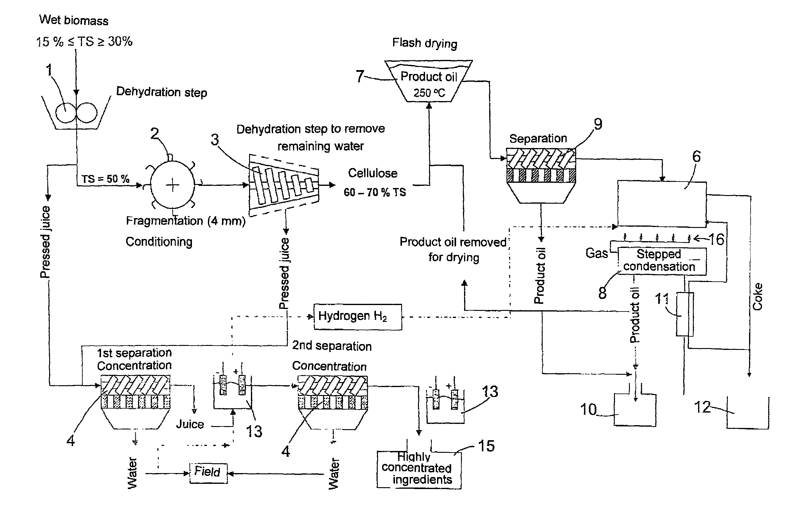
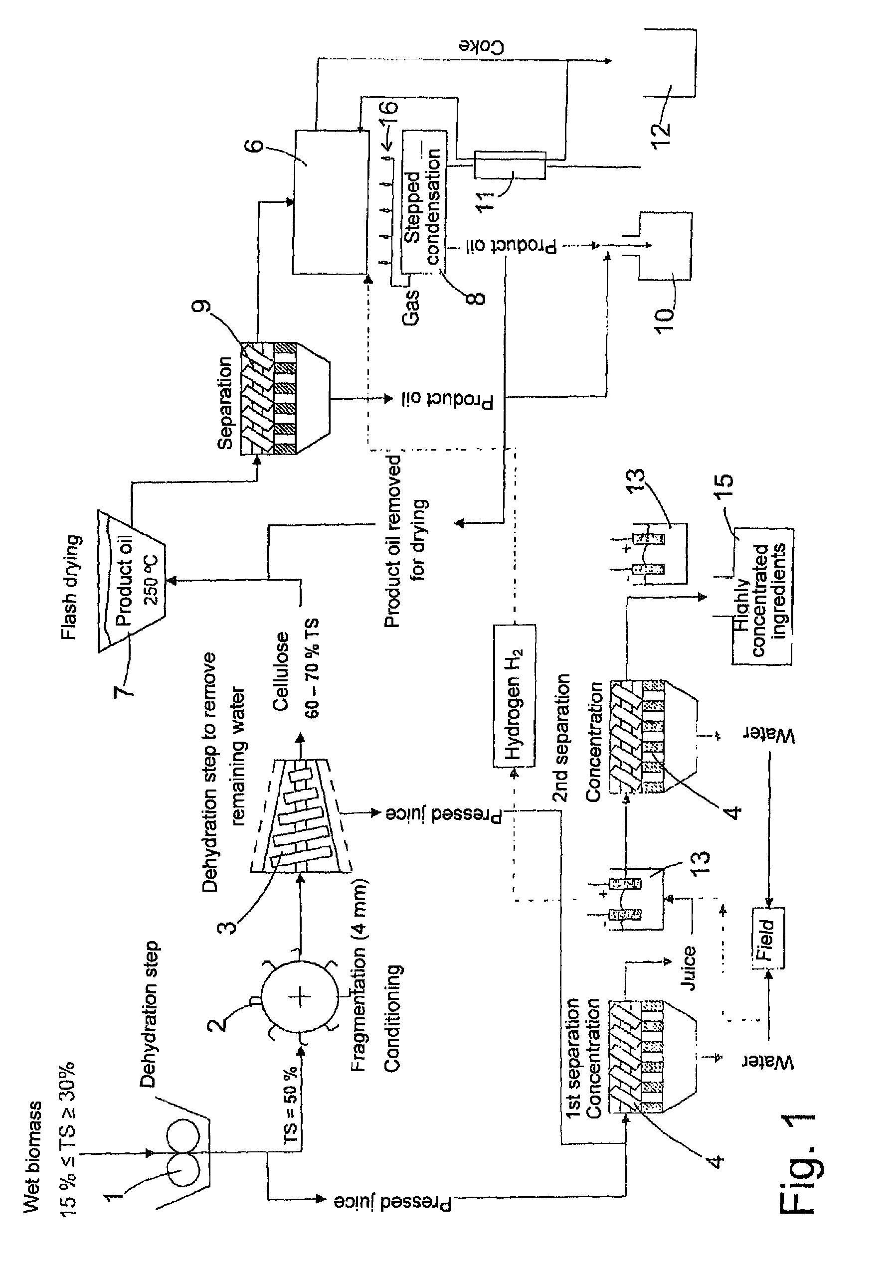
[0028]The devices shown in FIG. 1 and which are described in detail below are installed in a harvesting vehicle in accordance with a preferred embodiment of the present invention. An external view of the harvesting vehicle is not shown, since its external design—provided it is not that of a conventional combine harvester or a forage harvester—is dictated only by the requirement that the devices shown in FIG. 1 be accommodated therein. Akin to a conventional forage harvester or combine harvester, the harvesting vehicle includes a ground drive, on the front of which a crop material pick-up device is mounted in a replaceable manner. The crop material pick-up device is identical to that of a conventional forage harvester or combine harvester, and it may be used in a replaceable manner thereon and on the harvesting vehicle according to the present invention.

[0029]Two compression rollers 1 form a gap toward which the harvested biomass is conveyed by the pick-up device. Depending on the ty...


PUM

PropertyMeasurementUnit
sizeaaaaaaaaaa
temperatureaaaaaaaaaa
energy carriersaaaaaaaaaa

Abstract

A device for obtaining energy carriers from moist biomass includes a dehydration device for mechanically pre-dehydrating the biomass, and a drying step for post-dehydrating the pre-dehydrated biomass via the addition of heat. The dehydration device includes a first dehydration step and a second dehydration step, which is combined with the drying step to form a single assembly.

Description

CROSS-REFERENCE TO RELATED APPLICATION[0001]The invention described and claimed hereinbelow is also described in German Patent Application DE 10 2008 028 860.8 filed on Jun. 19, 2008. This German Patent Application, whose subject matter is incorporated here by reference, provides the basis for a claim of priority of invention under 35 U.S.C. 119(a)-(d).BACKGROUND OF THE INVENTION[0002]The present invention relates to the utilization of moist biomass as an energy source, in particular of grain and, above all, corn.[0003]Dry grain is used as an energy source in isolated cases, but doing so raises ethical concerns, because the grain could theoretically be used as a source of food for the human population. Grain that is harvested while moist, and that is traditionally used only as cattle feed, does not raise these ethical concerns. Corn, for instance, which is cultivated for use as livestock feed in many areas in Europe, often requires a longer vegetation time to mature than the climate...

Claims


Application Information

Patent Timeline
Patent Type & Authority Patents(United States)
IPC IPC(8): F26B3/34
CPCF26B7/00F26B23/00F26B1/00A01D43/00C10L5/445F26B5/14F26B11/14Y02E50/10Y02E50/30F26B2200/02C10L9/08Y02E50/14
Inventor WEIGELT, HORST
Owner CLAAS SELBSTFAHRENDE ERNTEMASCHINEN GMBH
Why Eureka
Try Eureka