Tiled lighting device

a lighting device and tile technology, applied in lighting support devices, lighting and heating apparatus, instruments, etc., can solve the problems of glare or bright spots or other loss, excessive and shortage of light in the end tile at the opposite side of the light guid

Inactive Publication Date: 2012-06-05
SIGNIFY HLDG BV
View PDF11 Cites 2 Cited by
  • Summary
  • Abstract
  • Description
  • Claims
  • Application Information

AI Technical Summary

Benefits of technology

[0007]Thus, there is disclosed a tiled lighting device comprising a central tile and at least one end tile forming part of a light guide. The light guide is preferably a light guide plate and may comprise additional tiles (central tiles or end tiles). The end tile is arranged at an edge of the light guide, while the central tile generally is surrounded by other tiles. The tiles are preferably arranged side by side and optically connected or aligned so that any in-coupled light can travel from one tile to a neighboring tile. The in-coupled light is provided by at least one solid state light source, and the light is introduced in a general direction towards or away from the end tile. The light source(s) may for example be side-emitting light source(s) arranged in the tiles or otherwise in connection with the tiles. The in-coupled light may then be mixed in the light guide before it is coupled out by means of a plurality of out-coupling structures. The out-coupling structures may for instance be tilted reflectors or the like arranged in the tiles or otherwise in connection with the tiles. However, since the light is in-coupled in a general direction, e.g. in essentially one direction, there may be a build up of excessive light in an end tile which is situated in the direction of the light compared to the rest of the light guide. This surplus of light may cause glare or bright spots or otherwise be lost. Likewise, there may be a shortage of light in an end tile at the opposite side of the light guide, i.e. an end tile situates “away” from the in-coupled light. This shortage may cause a dark rim or other dark area at the end tile. To this end, according to the present invention, the end tile has inherent in-coupling and / or inherent out-coupling of light different from the central tile, for producing a relative uniform overall emission of light from the tile lighting device without the above mentioned glare or bright spots or dark rims. Inherent in-coupling refers here to light introduced by any light source(s) arranged in (or for) the particular tile, while inherent out-coupling refers to extraction by any out-coupling structures arranged in (or for) the particular tile. The tiled lighting device according to the invention where a distinction is made between end tiles and central tiles has a superior performance compared to any tiled lighting device where all the tiles are the same.
[0010]To achieve the above mentioned changes in in-coupling / out-coupling, in one embodiment of the present invention, the first end tile may have a lower distribution density of light sources than the central tile (that is, a distribution density of the light sources is varied across the light guide according to areas where the light sources are located), so that less light is introduced in the end tile from its own light sources in order to reduce the surplus light causing the glare / bright spots or losses. In the extreme, the first end tile may have no light sources at all. Fewer or no light sources means that the first end tile becomes less expensive to manufacture. Instead of the omitted light sources, the “freed” space in the first end tile can be occupied by other electrical components. Such an electrical component is preferably common for the entire lighting device (i.e. it does not have to be reproduced for each tile), such as the lighting device's AC / DC converter (which may be necessary for supplying power to the light sources), a receiver for remote control of the lighting device (e.g. an infrared receiver or the like), batteries for off-line operation of the lighting device (which is beneficial in emergency lighting applications), an interface converter, etc. With respect to the second end tile, it may have a higher distribution density of light sources than the central tile to achieve the above mentioned higher inherent in-coupling. As an alternative (or in addition) to omitting / adding light sources, the lighting device may further comprise means for selectively controlling the brightness of at least one light source of the end tiles during operation. For the first end tile, the brightness may be decreased during operation. In the extreme, some or all of the light sources of the first end tile may be completely turned off during operation. For the second end tile, the brightness may be increased during operation. This again means that the amount of light introduced in the end tiles is adjusted, allowing a more uniform overall light emission from the light guide.
[0011]In another embodiment, the end tiles may have a higher distribution density of out-coupling structures than the central tile, so that more light may be out-coupled from the end tiles by their own out-coupling structures compared to the central tile. That is, a distribution density of the out-coupling structures is varied across the light guide according to areas where the out-coupling structures are located. In the first end tile, the higher out-coupling beneficially serves to extract surplus light in a controlled way to avoid the above mentioned bright spots / glare. In the second end tile, the higher out-coupling beneficially serves to extract more light in order to compensate for the above mentioned dark area. As an alternative (or in addition) to the extra out-coupling structures, the out-coupling structures of the end tiles may have a higher out-coupling capability than those of the central tile. The higher out-coupling capability may for example be realized by tilted reflectors having a larger reflective surface area, or by using reflective out-coupling structures having higher reflectance.
[0012]Preferably, the at least one solid state light source to be used in the tiled lighting device of the present inventions comprises a plurality of light emitting diodes (LEDs). LEDs have long lifetime, low operating voltage, are instantly turned on upon actuation, etc.

Problems solved by technology

However, since the light is in-coupled in a general direction, e.g. in essentially one direction, there may be a build up of excessive light in an end tile which is situated in the direction of the light compared to the rest of the light guide.
This surplus of light may cause glare or bright spots or otherwise be lost.
Likewise, there may be a shortage of light in an end tile at the opposite side of the light guide, i.e. an end tile situates “away” from the in-coupled light.
This shortage may cause a dark rim or other dark area at the end tile.

Method used


Image

  • Tiled lighting device
  • Tiled lighting device
  • Tiled lighting device

Examples


Embodiment Construction

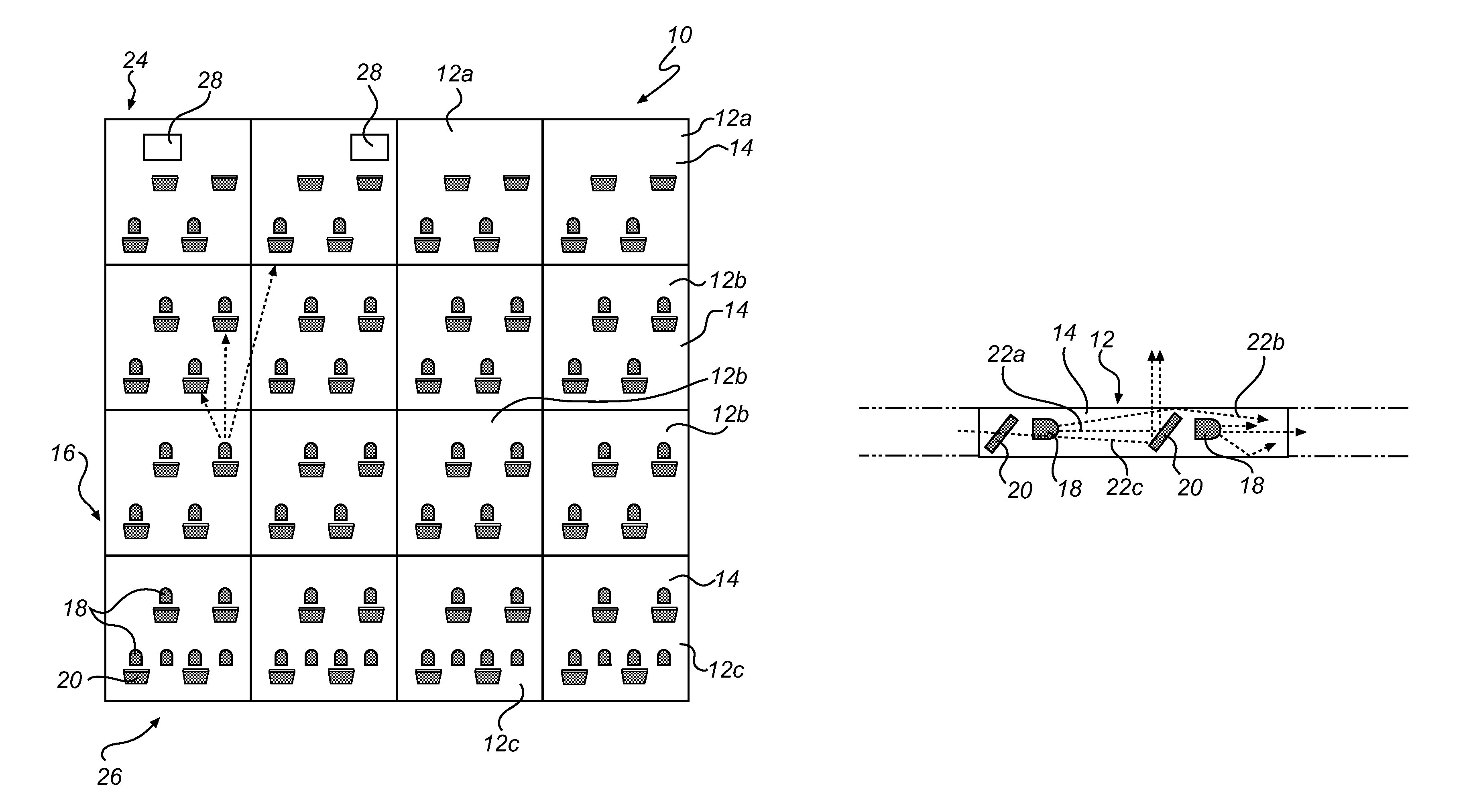
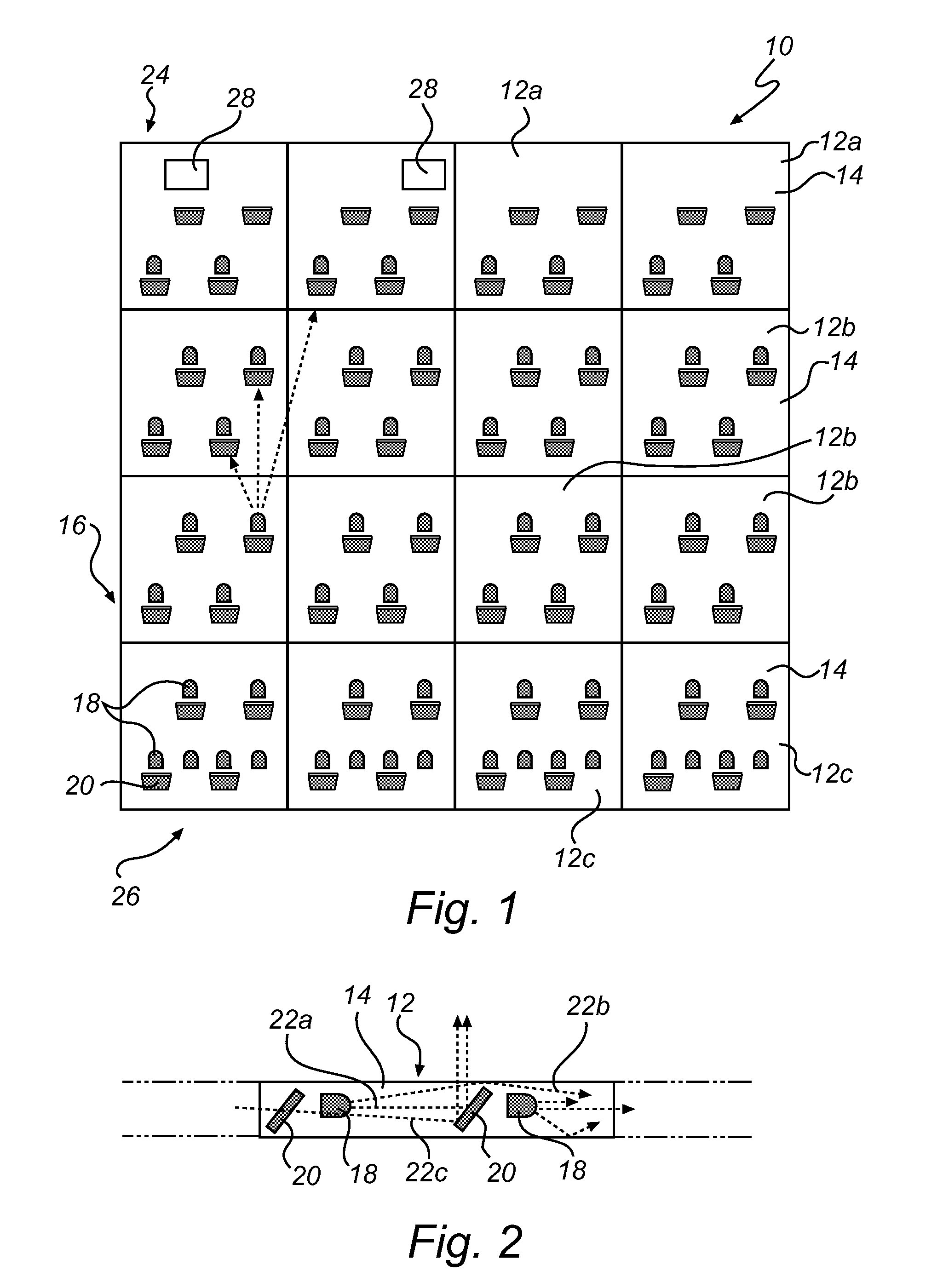
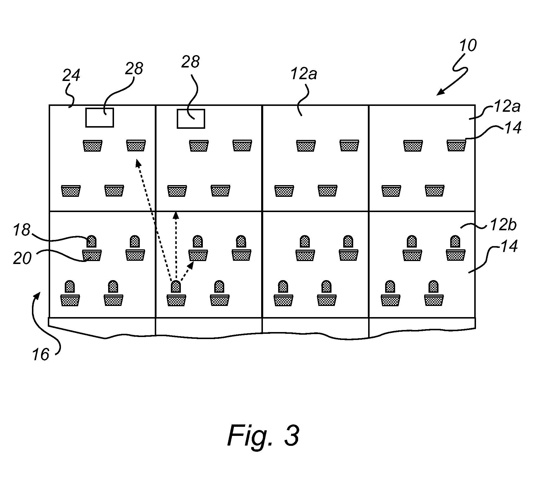
[0021]FIG. 1 illustrates a tiled lighting device 10 according to the invention. The lighting tiled device 10 is build up of a plurality of modules or tiles generally designated 12. Depending on the number and size of tiles 12 and how they are arranged, the lighting device 10 may have virtually any size and shape, making it more versatile than a common luminary having a fixed size and shape. For instance, the lighting device 10 may be customized to cover a certain area or to fit in a certain space. In FIG. 1, the exemplary tiled lighting device 10 is made up of 4×4 tiles 12, all having essentially the same size and shape.

[0022]Each tile 12 in the lighting device 10 of FIG. 1 comprises a square, transparent or translucent sub-light guide plate 14. Other forms may be used, such as rectangular tiles, and the not all tiles in the lighting device have to be of the same shape and size. The transparent or translucent sub-light guide plate 14 may be made of glass or plastics.

[0023]The tiles ...


PUM


Abstract

The present invention relates to a lighting device (10) comprising a tiled light guide (16) comprising a central tile (12b) and at least one end tile (12a, 12c), the end tile(s) (12a, 12c) being arranged at an edge (24, 26) of the light guide (16); at least one solid state light source (18) arranged for coupling light into the light guide (16) in a general direction towards or away from the end tile(s) (12a, 12c); and a plurality of out-coupling structures (20) arranged for coupling light out of the light guide (16); wherein the end tile(s) (12a, 12c) has inherent in-coupling and / or inherent out-coupling of light different from the central tile (12b).

Description

FIELD OF THE INVENTION[0001]The present invention relates to a tiled lighting device.BACKGROUND OF THE INVENTION[0002]Progress in the brightness, lumen efficacy and affordability of solid state light sources such as light emitting diodes (LEDs) enables new lighting applications that are no longer restricted to niche markets. LEDs offer several advantages over traditional light sources, such as long lifetime, low operating voltage, instant on, etc. For these and other reasons, LEDs are becoming more and more suited for making lamps for several applications such as color variable lamps, spotlights, LCD backlighting, architectural lighting, stage lighting, etc.[0003]For many lighting applications, the light of a single LED is not sufficient, and light of multiple LEDs needs to be combined to form a light source. Hereto, US2005 / 0116667 (Mueller et al.) discloses a tiled lighting system with LEDs, wherein a plurality of alike light tiles are arranged side by side and interconnected to ti...

Claims


Application Information

Patent Timeline
Patent Type & Authority Patents(United States)
IPC IPC(8): F21V7/04
CPCE04F13/08F21S2/00G02B6/0078F21V33/006E04F2290/026F21Y2101/02G02B6/0068F21Y2115/10
Inventor DEURENBERG, PETER HUBERTUS FRANCISCUSVISSENBERG, MICHEL CORNELIS JOSEPHUS MARIEIJZERMAN, WILLEM LUBERTUSBOONEKAMP, ERIK
Owner SIGNIFY HLDG BV
Why Eureka
Try Eureka