Condenser microphone

a condenser microphone and microphone housing technology, applied in the direction of piezoelectric/electrostrictive transducers, mouthpiece/microphone attachments, microphone structural associations, etc., can solve the problems of high-frequency current intruding into the microphone housing through the connecting part, vibration noise may be generated, and audible frequency nois

Inactive Publication Date: 2012-06-05
AUDIO-TECHNICA
View PDF37 Cites 11 Cited by
  • Summary
  • Abstract
  • Description
  • Claims
  • Application Information

AI Technical Summary

Benefits of technology

[0013]According to the present invention, since the extraction electrode of the backplate on the microphone side is in planar contact with the gate of the FET on the microphone main body side with a large area via the conductive elastic material such as a conductive cloth, the contact resistance value is reduced accordingly, and a stable connecting state can be formed. Also, since the ferrite material is disposed so as to surround the conductive elastic material, a high-frequency current caused by external electromagnetic waves can be prevented from flowing to the gate of the FET.
[0015]Also, since the ferrite material is fixed, as the cylindrical ferrite beads, on the circuit board via the electrical insulating holding ring, vibrating noise caused by mechanical vibrations of the ferrite beads and leak noise caused by the contact with the gate of the FET can be prevented from being generated.

Problems solved by technology

Therefore, when a high-frequency current caused by external electromagnetic waves (especially, electromagnetic waves emitted from a cellular phone) is applied to the electronic circuit, the current is detected by the FET, and noise of an audible frequency may be generated.
However, for the condenser microphone of a type such that a microphone capsule is exchangeable with respect to a microphone main body, since electrical connection is made in a mechanically connected portion, the high-frequency current is liable to intrude into the microphone housing through the connecting part.
However, since the gate part of FET has a high impedance, vibrating noise may be generated if the ferrite beads vibrate mechanically, and leak noise may be generated if the electrical insulation is insufficient.

Method used


Image

  • Condenser microphone
  • Condenser microphone

Examples


Embodiment Construction

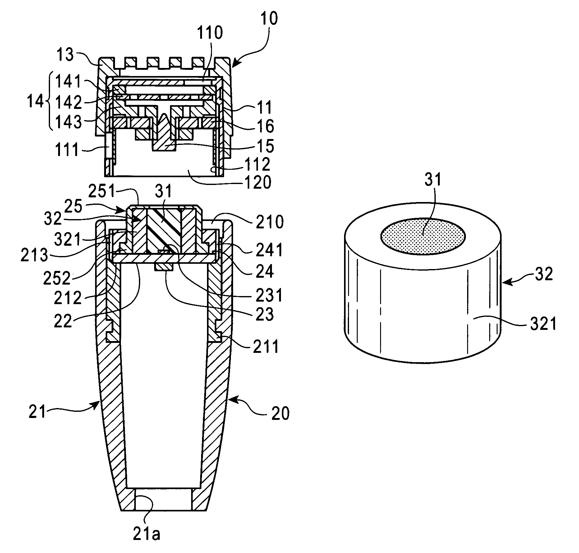
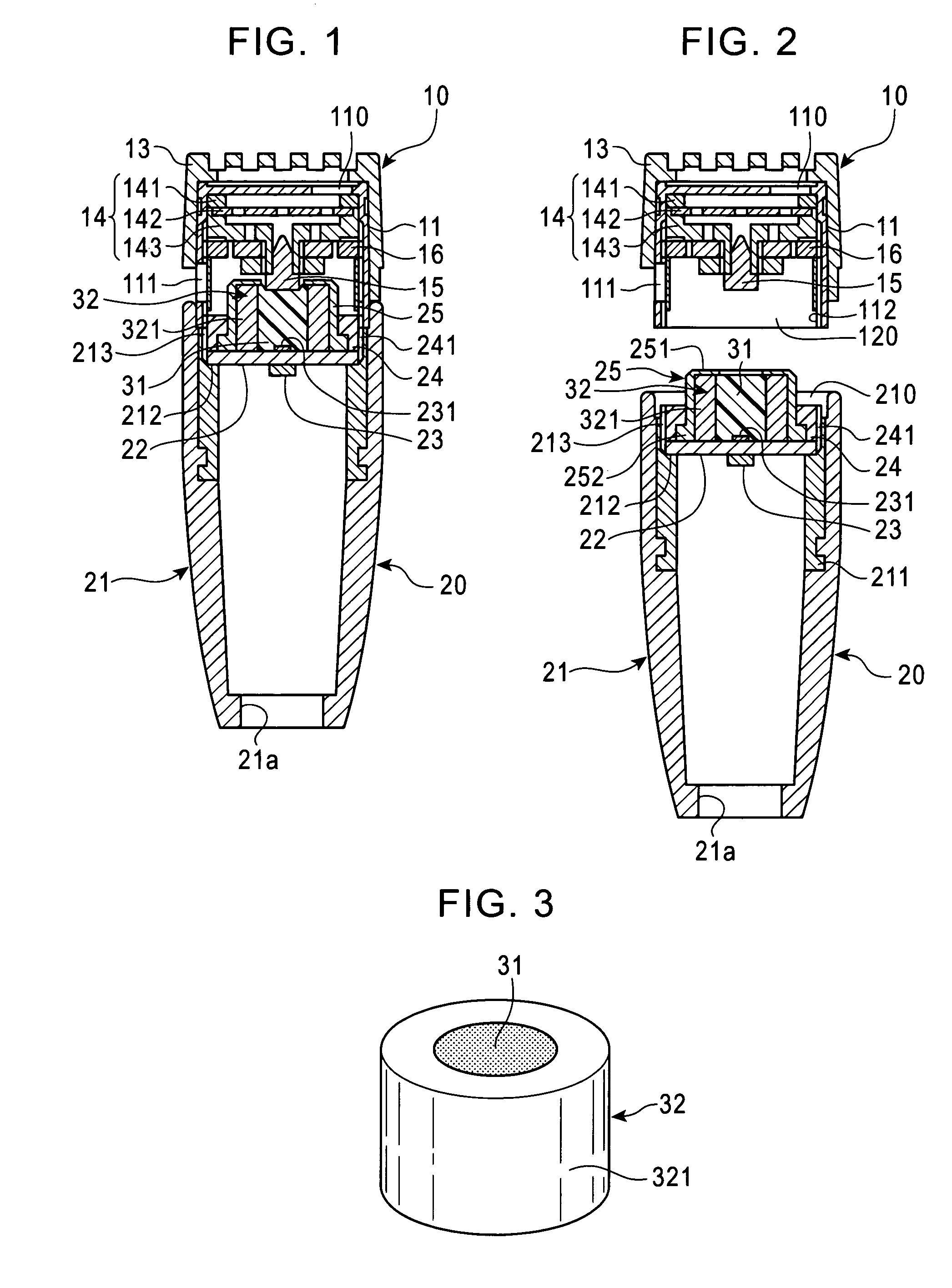
[0019]An embodiment of the present invention will now be described with reference to FIGS. 1 to 3. The present invention is not limited to this embodiment.

[0020]Referring to FIGS. 1 and 2, a condenser microphone in accordance with the present invention includes a microphone capsule 10 and a microphone main body 20, and is configured so that the microphone capsule 10 can be exchanged according to a desired directionality.

[0021]The microphone capsule 10 is provided with a capsule housing 11 formed of a metallic cylindrical body. On one end surface (the upper end surface in FIGS. 1 and 2) side of the capsule housing 11, a front acoustic terminal 110 is provided, and the other end surface (the lower end surface in FIGS. 1 and 2) side thereof serves as an opening part 120.

[0022]In this example, since the microphone capsule 10 is unidirectional, a rear acoustic terminal 111 is provided on the side surface of the capsule housing 11. Also, on one end surface side of the capsule housing 11, ...


PUM


Abstract

There is provided a condenser microphone in which electromagnetic shielding in the connecting part of a microphone capsule and a microphone main body is made more reliable. In the condenser microphone including a microphone capsule 10 and a microphone main body 20, the microphone capsule 10 being configured so that an electrostatic acoustic-electric converter is accommodated in a metallic capsule housing 11, and an extraction electrode 15 of a backplate 142 is disposed in substantially the central portion of a connection-side opening part 120, and the microphone main body 20 being configured so that a circuit board 22 is disposed at a predetermined depth position in a connection-side opening part 210 of a metallic microphone housing 21 to which the capsule housing 11 is detachably connected, and a field effect transistor 23 and a conductive contacting means for connecting the gate of the field effect transistor 23 to the extraction electrode 15 are disposed; and configured so that the extraction electrode 15 is connected to the gate of the field effect transistor 23 via the conductive contacting means with the connection of the capsule housing 11 to the microphone housing 21, as the conductive contacting means, a conductive elastic material 31 such as a conductive resin foam or a conductive cloth is used, and a ferrite material 32 is disposed on the circuit board 22 so as to surround the conductive elastic material 31.

Description

CROSS-REFERENCE TO RELATED APPLICATION[0001]The present application is based on, and claims priority from, Japanese Application Serial Number JP2009-162343, filed Jul. 9, 2009, the disclosure of which is hereby incorporated by reference herein in its entirety.TECHNICAL FIELD[0002]The present invention relates to a condenser microphone in which a microphone capsule is exchangeable with respect to a microphone main body. More particularly, it relates to an electromagnetic shielding technique in a connecting part of the condenser microphone.BACKGROUND ART[0003]For the condenser microphone, an electrostatic acoustic-electric converter provided in a microphone unit has a very high impedance. Therefore, the microphone incorporates an electronic circuit including an impedance converter. As the impedance converter, a field effect transistor (FET) has usually been used.[0004]Therefore, when a high-frequency current caused by external electromagnetic waves (especially, electromagnetic waves e...

Claims


Application Information

Patent Timeline
Patent Type & Authority Patents(United States)
IPC IPC(8): H04R25/00
CPCH04R1/04H04R1/08H04R19/04
Inventor AKINO, HIROSHI
Owner AUDIO-TECHNICA
Why Eureka
Try Eureka