
Broadband power amplifier

a power amplifier and broadband technology, applied in amplifiers, amplifiers with semiconductor devices/discharge tubes, amplifiers, etc., can solve the problems of increasing the cost of passive devices, increasing the efficiency of circuits, and increasing the cost of chips and circuits, etc., and achieve the effect of simple circuit structur

Active Publication Date: 2012-06-12
WIPAM
View PDF22 Cites 9 Cited by
  • Summary
  • Abstract
  • Description
  • Claims
  • Application Information

AI Technical Summary

Benefits of technology

[0014]It is, therefore, an object of the present invention is to provide a power amplifier that is advantageous in view of integration and miniaturization due to the low characteristic impedance of a quarter wave transformer and has a simple circuit structure while showing the broadband characteristics.
[0015]Another object of the present invention is to provide a power amplifier that has a simple circuit structure while showing the broadband characteristics by realizing a substantially two-section input matching circuit using a quarter wave transformer itself as the input matching circuit.
[0022]In accordance with the present invention, the broadband power amplifier is advantageous in view of integration and miniaturization due to the low characteristic impedance of a quarter wave transformer and enables both reduction of sizes of chips and circuits due to its simple circuit structure and reduction in cost due to the reduced number of passive devices, by realizing a substantially two-section output matching circuit or a substantially two-section input matching circuit using the quarter wave transformer itself as the input matching circuit or the input matching circuit. Further, the broadband power amplifier enables improvement in the efficiency of a circuit by reducing the matching circuit loss of the entire circuit due to losses in passive devices.

Problems solved by technology

In this case, the circuit structure becomes complex as the number of matching circuits increases, causing the sizes of chips and circuits to become larger and causing increase in cost owing to additional use of passive devices.
Then, as the number of passive devices increases, the matching circuit loss in the entire circuit increases due to loss in the passive devices, thereby causing lowering of the efficiency of the circuit.
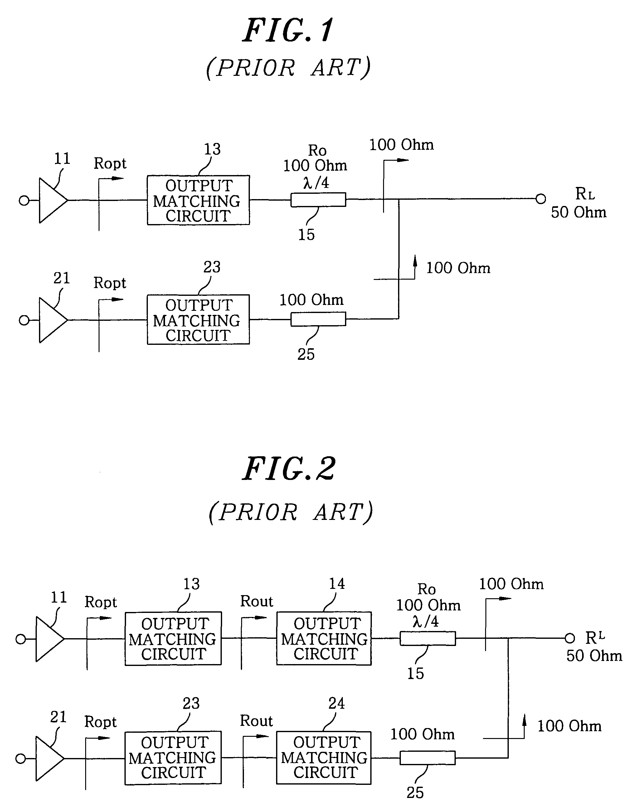
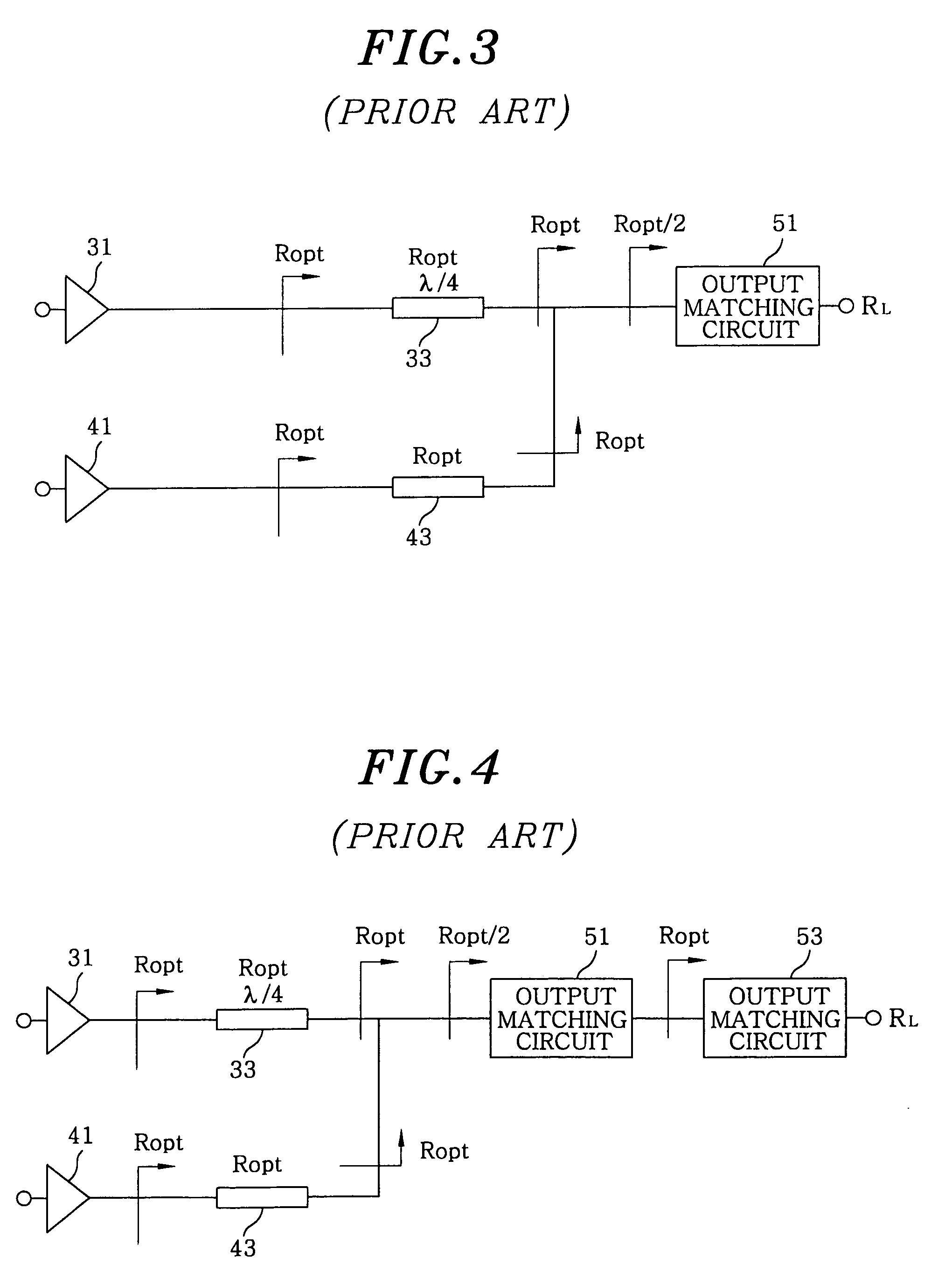
The first to third examples of FIG. 2, FIG. 4, and FIG. 5 use two-section output matching circuits to widen the bandwidths of frequencies, thereby obtaining the broadband characteristics, in which case the structures thereof are complex, causing large sizes of chips and circuits, and the matching circuit loss of all the circuits increases due to the losses in passive devices, causing lowering of the efficiencies of the circuits.
In particular, the first example of the prior art is vulnerable in integration and miniaturization due to a high characteristic impedance of a micro-strip line functioning as a quarter wave transformer when it is used as a power amplifier for a mobile communication terminal.
Further, even when a Doherty power amplifier is employed on a package of a printed circuit board in order to realize a power amplifier for a mobile communication terminal, the size of the package and the manufacturing cost increase due to the use of several passive devices.
In addition to disadvantages in view of miniaturization of such a power amplifier, the broadband characteristics of a power amplifier may limit the adoption of power amplifiers that are to be used in the next generation mobile communication system.

Method used


Image

  • Broadband power amplifier
  • Broadband power amplifier
  • Broadband power amplifier

Examples


first embodiment

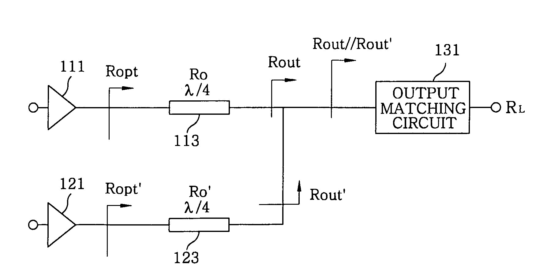
[0035]Referring first to FIG. 6, a broadband power amplifier according to the present invention includes a first amplifier 111 and a second amplifier 121 that are connected in parallel, a first quarter wave transformer 113 connected to an output terminal of the first amplifier 111 to perform an output matching function through control of the load line impedance of the first amplifier 111, a second quarter wave transformer 123 connected to an output terminal of the second amplifier 121 to perform an output matching function through control of the load line impedance of the second amplifier 121, and an output matching circuit 131 connected to rear ends of the first quarter wave transformer 113 and the second quarter wave transformer 123.

[0036]According to the first embodiment of the present invention, the first and the second quarter wave transformers 113 and 123 includes first and second micro-strip lines, respectively. In addition, the first amplifier 111 and the second amplifier 12...

second embodiment

[0047]Alternatively, one or more inductors L in the π-networks 115 and 125 and the T-networks 117 and 127 of the second embodiment may be realized by small inductors such as micro-strip lines or by bondwire inductors (for example, bonding wire inductors) essential for connection of MMIC chips to modules, in order to improve the complexity of the circuits, costs, and losses of the matching circuits.

[0048]FIGS. 9 to 11 are circuit diagrams of broadband power amplifiers for output matching in accordance with fourth to sixth embodiments of the present invention.

[0049]Referring first to FIG. 9, a broadband power amplifier of the fourth embodiment includes a first amplifier 211 and a second amplifier 221 that are connected in parallel to induce a Doherty operation, a first quarter wave transformer 213 connected to an output terminal of the first amplifier 211 to perform an output matching function through control of the load line impedance of the first amplifier 211, and a second quarter ...

fourth embodiment

[0050]According to the present invention, the first and the second quarter wave transformers 213 and 225 include first and second micro-strip lines, respectively. In addition, the first amplifier 211 and the second amplifier 221 may include a carrier amplifier and a peaking amplifier, respectively, or vice versa.

[0051]Referring now to FIG. 10, a broadband power amplifier according to the fifth embodiment of the present invention is identical to that of the fourth embodiment, except that the quarter wave transformer are realized by π-networks 215 and 227, respectively. Each of the π-networks 215 and 227 includes an inductor-capacitor circuit having an inductor L and capacitors C. Although one inductor L and two capacitors C are employed to realize each π-network 215 and 227 in FIG. 10, two inductors L and one capacitor C may be employed to realize a π-network. For example, a capacitor C may be disposed at the locations of the inductors L of the π-network 215 and inductors L may be di...


PUM


Abstract

A broadband power amplifier is embodied by realizing a substantially two-section output matching circuit or a substantially two-section input matching circuit using a quarter wave transformer itself as the input matching circuit or the output matching circuit. The broadband power amplifier is advantageous in view of integration and miniaturization due to the low characteristic impedance of the quarter wave transformer and enables both reduction of sizes of chips and circuits due to its simple circuit structure and reduction in cost due to the reduced number of passive devices.

Description

[0001]This application is a Continuation Application of PCT International Application No. PCT / KR2008 / 004518 filed on Aug. 4, 2008, which designated the United States.FIELD OF THE INVENTION[0002]The present invention generally relates to a broadband power amplifier and, more particularly, to a broadband power amplifier employing a simple circuit structure while having broadband characteristics and being advantageous in view of integration and miniaturization.BACKGROUND OF THE INVENTION[0003]In recent years, due to miniaturization and multi-functionality of mobile communication terminals, relays, and base stations, many studies on improvement in the efficiencies of RF power amplifiers that consume almost all consumption power are being carried out in an effort to increase battery time, and, among them, studies on Doherty power amplifier, which is representative of solution for increasing efficiency of a RF power amplifier, are mainly carried out.[0004]The Doherty amplifier was provide...

Claims


Application Information

Patent Timeline
Patent Type & Authority Patents(United States)
IPC IPC(8): H03F3/68
CPCH03F1/0288H03F1/42H03F1/56H03F3/195H03F3/211H03F3/602H03F2200/387H03F2203/21139H03F1/07H03F3/20
Inventor YU, DAEKYU
Owner WIPAM
Learn More