Omni directional broadband coplanar antenna element

a broadband, coplanar technology, applied in the direction of individual energised antenna array, resonant antenna, radiating element structure, etc., can solve the problems of difficulty in maintaining a desired broad frequency bandwidth and omni-directional beamwidth

Active Publication Date: 2012-06-12
INTEL CORP
View PDF24 Cites 9 Cited by
  • Summary
  • Abstract
  • Description
  • Claims
  • Application Information

AI Technical Summary

Problems solved by technology

However it is difficult to maintain a desired broad frequency bandwidth and also provide an omni-directional beamwidth.

Method used


Image

  • Omni directional broadband coplanar antenna element
  • Omni directional broadband coplanar antenna element
  • Omni directional broadband coplanar antenna element

Examples


Embodiment Construction

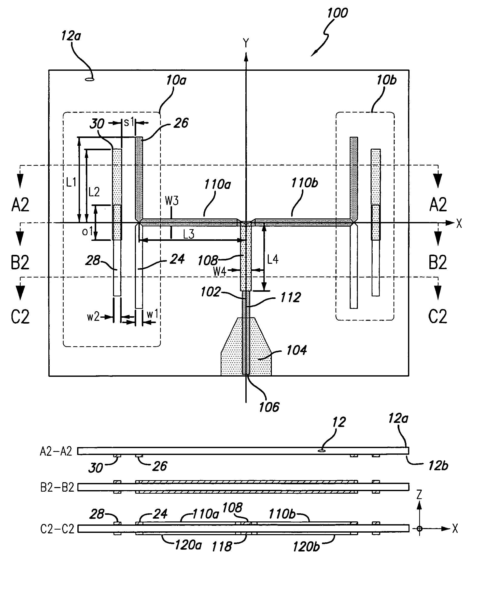
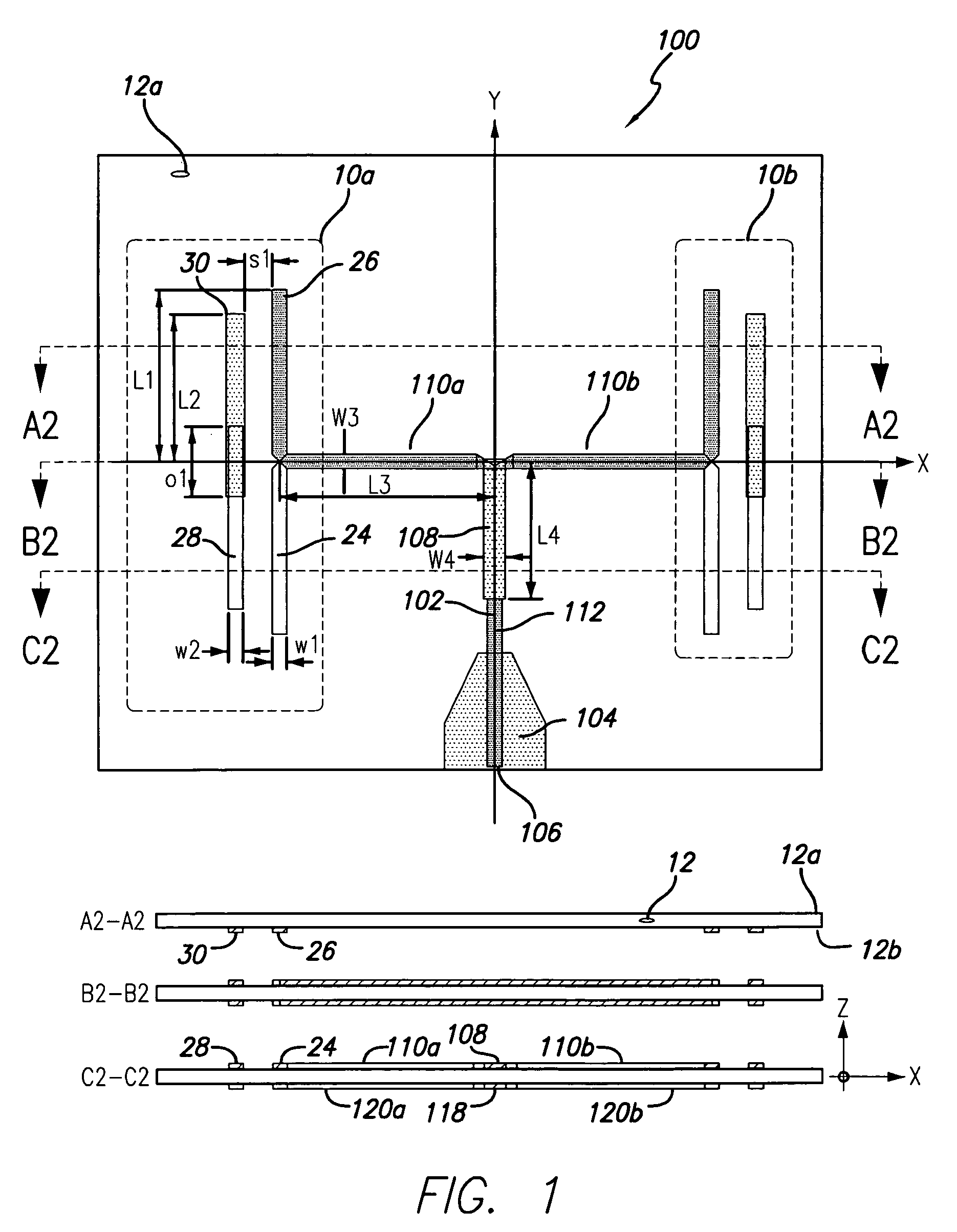
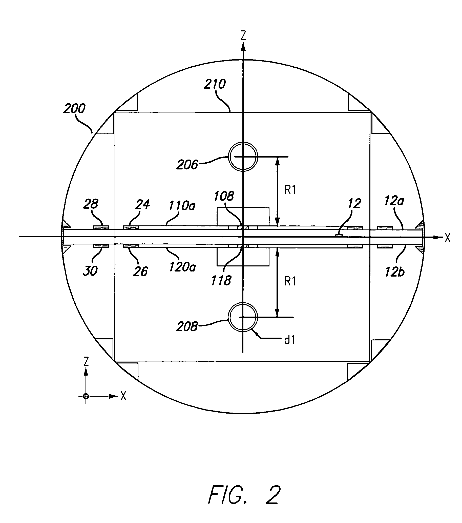
[0024]One object of the present invention is to provide dielectric based coplanar antenna elements which have broad frequency bandwidth and are easy to fabricate using conventional PCB processes. The present invention may preferably utilize a radiating element structure described in patent application Ser. No. 12 / 212,533 filed Sep. 17, 2008 and provisional patent application No. 60 / 994,557 filed Sep. 20, 2007, the disclosures of which are incorporated herein by reference in their entirety. In addition to coplanar radiating elements the present invention preferably takes advantage of pattern augmentation rods positioned in near proximity to the dielectric plane, equidistant to each surface side. To achieve an omni-directional radiation pattern a pair of symmetrically opposing radiating elements are preferably fed by a balanced feed network structure. The balanced feed structure provides equal signal division for each radiating element to achieve a symmetric radiation pattern. Additio...


PUM


Abstract

The present invention provides an omni-directional antenna element configuration having a compensated radiation pattern. Broadband antenna elements are coplanarly disposed on a suitable planar dielectric material. A single element omni-directional antenna comprises a pair of balanced fed radiating microstrip elements symmetrically disposed about the centerline of a balanced signal feed network. Additionally, a pair of pattern augmentation rods are positioned on each side of and proximate to the planar dielectric material running longitudinally to the centerline axis of a balanced feed network. Disposed proximate to each radiating element are partially coplanar, frequency bandwidth expanding microstrip lines. The combination of radiating elements together with pattern augmentation rods provides a broad bandwidth omni-directional radiating element suitable for use in multi-element antenna arrays.

Description

RELATED APPLICATION INFORMATION[0001]The present application claims priority under 35 USC section 119(e) to U.S. provisional patent application Ser. No. 60 / 998,662 filed Oct. 12, 2007, the disclosure of which is incorporated herein by reference in its entirety.BACKGROUND OF THE INVENTION[0002]1. Field of the Invention[0003]The present invention relates in general to radio communication systems and components. More particularly the invention is directed to antenna elements and antenna arrays for radio communication systems.[0004]2. Description of the Prior Art and Related Background Information[0005]Modern wireless antenna implementations generally include a plurality of radiating elements that may be arranged to provide a desired radiated (and received) signal beamwidth and azimuth scan angle. For an omni-directional antenna it is desirable to achieve a near uniform beamwidth that exhibits a minimum variation over 360 degrees of coverage. Differing from highly directional antennas a...

Claims


Application Information

Patent Timeline
Patent Type & Authority Patents(United States)
IPC IPC(8): H01Q19/10
CPCH01Q1/24H01Q1/38H01Q9/16H01Q21/12H01Q25/005H01Q1/241H01Q1/246H01Q1/42
Inventor SEMONOV, KOSTYANTYNRABINOVICH, ALEXANDERVASSILAKIS, BILL
Owner INTEL CORP
Why Eureka
Try Eureka