
Ultrasonic diagnostic apparatus, ultrasonic image processing apparatus, and ultrasonic image processing method

a diagnostic apparatus and ultrasonic technology, applied in diagnostics, medical science, instruments, etc., can solve the problems of limited performance, interference of adjacent tissues of a tested body, and the dependence of the obtained image on artificial sensibility, so as to achieve the effect of removing the speckle of two-dimensional or three-dimensional ultrasonic image data more effectively and high speed

Active Publication Date: 2012-06-19
TOSHIBA MEDICAL SYST CORP
View PDF3 Cites 8 Cited by
  • Summary
  • Abstract
  • Description
  • Claims
  • Application Information

AI Technical Summary

Benefits of technology

"The present invention provides an ultrasonic diagnostic apparatus and method that can effectively and quickly remove speckle from two-dimensional or three-dimensional ultrasonic image data. This is achieved by performing hierarchical multiresolution decomposition of the ultrasonic image data, acquiring low-frequency and high-frequency decomposed image data with edge information, controlling the signal level of the high-frequency decomposed image data based on the edge information, and performing hierarchical multiresolution mixing of the output data from a filtering unit and the high-frequency level control unit. This results in a more accurate and reliable ultrasonic image that can be used for diagnosis and treatment purposes."

Problems solved by technology

However, received signals from a plurality of adjacent tissues of a tested body interfere with each other due to a phase difference thereof.
Since this speckle interferes with correctly observing the position and shape of a boundary of tissues of the tested body, various kinds of processing methods for removing the speckle have been proposed.
Although a speckle is removed in this method, there is a problem that an obtained image depends on artificial sensibility.
Also in this case, however, there is a limitation in performance because making the edge smooth and clear is performed by a fixed filter.
However, since the nonlinear anisotropic diffusion filter needs an operation of solving a partial differential equation for calculation, there is a problem that it takes a time for the calculation processing.
In addition, although there is an effect of reducing the speckle to some extent with the single nonlinear anisotropic diffusion filter, there is also a problem that the effect is not enough.
In this case, a problem occurs, for example, when only a B-mode image of an image displayed by overlapping the B-mode image and a color Doppler image each other.
This makes it difficult to increase the processing speed.

Method used


Image

  • Ultrasonic diagnostic apparatus, ultrasonic image processing apparatus, and ultrasonic image processing method
  • Ultrasonic diagnostic apparatus, ultrasonic image processing apparatus, and ultrasonic image processing method
  • Ultrasonic diagnostic apparatus, ultrasonic image processing apparatus, and ultrasonic image processing method

Examples


first embodiment

[0023]An embodiment of the present invention will now be described with reference to the accompanying drawings. Moreover, in the following description, components having approximately the same function and configuration are denoted by the same reference numeral, and a repeated explanation will only be made as needed.

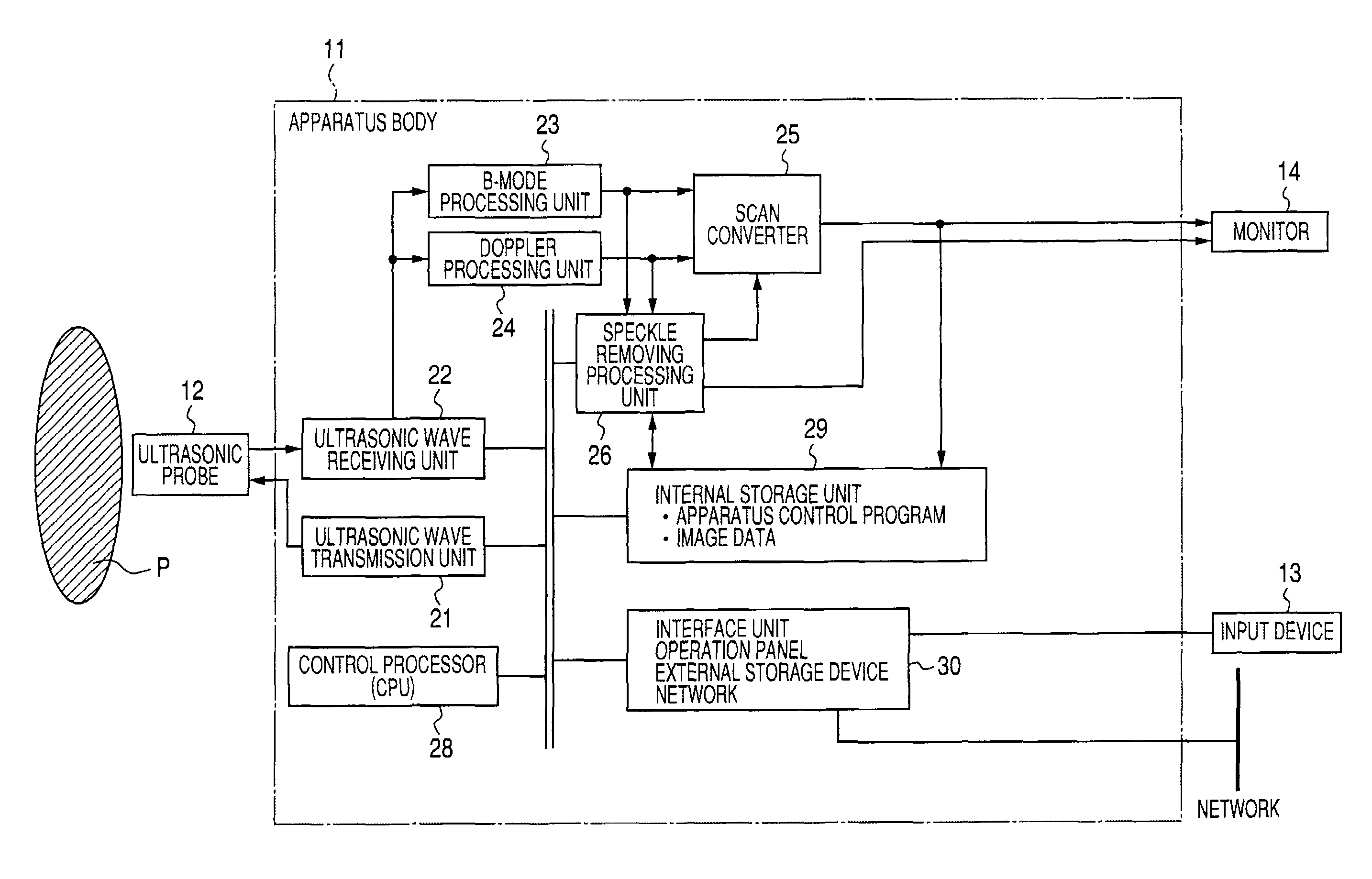
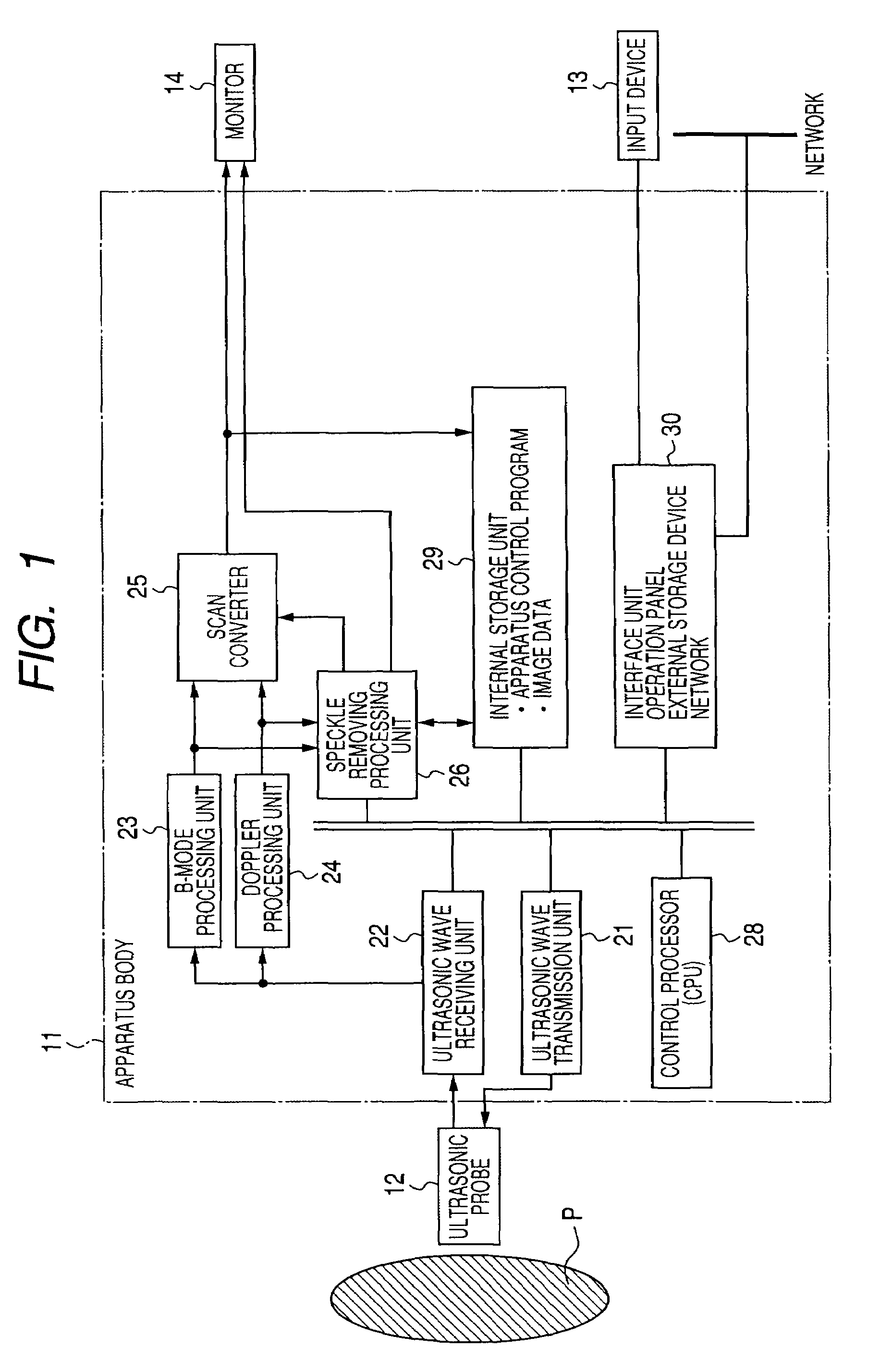
[0024]FIG. 1 is a block diagram illustrating the configuration of an ultrasonic diagnostic apparatus 1 according to the present embodiment. As shown in the drawing, an ultrasonic diagnostic apparatus 1 includes an ultrasonic probe 12, an input device 13, a monitor 14, an ultrasonic wave transmission unit 21, an ultrasonic wave receiving unit 22, a B-mode processing unit 23, a Doppler processing unit 24, a scan converter 25, a speckle removing processing unit 26, a control processor (CPU) 28, an internal storage unit 29, and an interface unit 30. Hereinafter, functions of the constituent components will be described.

[0025]The ultrasonic probe 12 generates an ultrasonic wa...

second embodiment

[0068]In the first embodiment, an example in which speckle removing processing is executed on two-dimensional image data (raw data) has been illustrated. On the other hand, in the present embodiment, a case in which an ultrasonic diagnostic apparatus 1 executes speckle removing processing on three-dimensional volume data (raw data) will be described.

[0069]FIG. 4 is a view illustrating the configuration of the ultrasonic diagnostic apparatus 1 according to the present embodiment. The configuration shown in FIG. 4 is different from that shown in FIG. 1 in that a volume data generating unit 31 is further provided and a speckle removing processing unit 26 performs speckle removing processing on volume data from the volume data generating unit 31.

[0070]The volume data generating unit 31 generates B-mode volume data using B-mode image data received from a B-mode processing unit 23. In addition, the volume data generating unit 31 generates Doppler-mode image volume data using Doppler-mode ...

third embodiment

[0076]As described above, in the second embodiment, an example in which the present invention is applied to the three-dimensional volume data before three-dimensional image processing has been illustrated. However, in a third embodiment, an example in which the present invention is applied to a three-dimensional display after three-dimensional image processing will now be illustrated.

[0077]In the second embodiment, an example in which speckle removing processing is executed on B-mode volume data before three-dimensional image processing has been illustrated. On the other hand, in the present embodiment, a case in which an ultrasonic diagnostic apparatus 1 executes speckle removing processing on image data after three-dimensional image processing will be described.

[0078]FIG. 6 is a view illustrating the configuration of the ultrasonic diagnostic apparatus 1 according to the present embodiment. The configuration shown in FIG. 6 is different from that shown in FIG. 4 in that a volume d...


PUM


Abstract

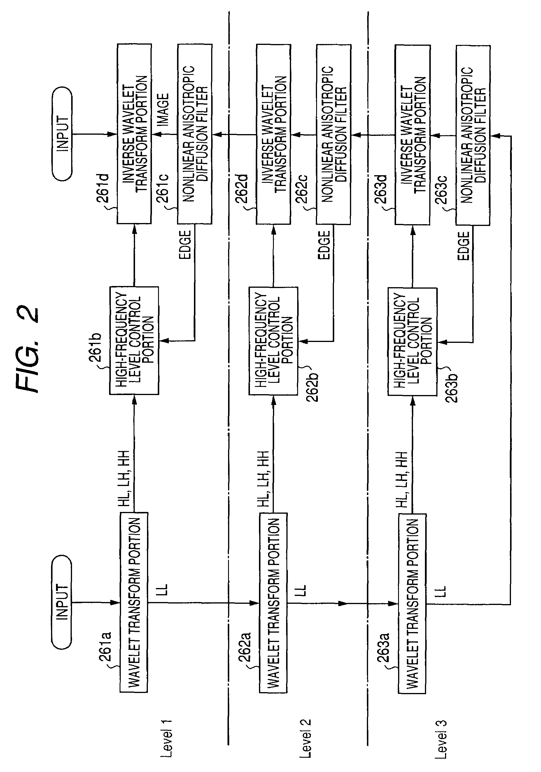
Multiresolution decomposition of image data before scan conversion processing is hierarchically performed, low-frequency decomposed image data and high-frequency decomposed image data with first to n-th levels are acquired, nonlinear anisotropic diffusion filtering is performed on output data from a next lower layer or the low-frequency decomposed image data in a lowest layer, and filtering for generating edge information on a signal for every layer is performed from the output data from the next lower layer or the low-frequency decomposed image data in the lowest layer. In addition, on the basis of the edge information on each layer, a signal level of the high-frequency decomposed image data is controlled for every layer and multiresolution mixing of the output data of the nonlinear anisotropic diffusion filter and the output data of the high-frequency level control, which are obtained in each layer, are hierarchically performed.

Description

CROSS-REFERENCE TO RELATED APPLICATIONS[0001]This application is based upon and claims the benefit of priority from prior Japanese Patent Application No. 2007-338276, filed Dec. 27, 2007, the entire contents of which are incorporated herein by reference.BACKGROUND OF THE INVENTION[0002]1. Field of the Invention[0003]The present invention relates to an ultrasonic diagnostic apparatus, an ultrasonic image processing apparatus, and an ultrasonic image processing method of transmitting an ultrasonic wave to the inside of a tested body and obtaining diagnostic information inside the tested body on the basis of a reflected wave from the inside of the tested body. In particular, the present invention relates to removing of a speckle included in image data.[0004]2. Description of the Related Art[0005]The ultrasonic diagnosis makes it possible that the pulsation of the heart or the movement of an embryo is displayed in real time by a simple operation of bringing an ultrasonic probe into cont...

Claims


Application Information

Patent Timeline
Patent Type & Authority Patents(United States)
IPC IPC(8): A61B8/00G06K9/00
CPCA61B8/08
Inventor OSUMI, RYOTASATO, TAKESHI
Owner TOSHIBA MEDICAL SYST CORP
Learn More