Reduced-pressure drying method, method of manufacturing functional film, method of manufacturing electro-optic device, electro-optic device, liquid crystal display device, organic el display device, and electronic apparatus

a technology of functional film and reduced pressure, which is applied in the direction of drying machines, lighting and heating equipment, instruments, etc., can solve the problems of in-plane distribution of film thickness, difficulty in drying liquid substances, and uneven thickness of film thicknesses

Inactive Publication Date: 2012-06-19
SEIKO EPSON CORP
View PDF11 Cites 16 Cited by
  • Summary
  • Abstract
  • Description
  • Claims
  • Application Information

AI Technical Summary

Benefits of technology

[0010]The invention addresses the technical problems described above, and has an advantage of providing a reduced-pressure drying method capable of optimizing the evaporation rate of the solvent in the applied liquid substance in the drying process in accordance with the type of the liquid substance, and of performing the reduced-pressure drying in a condition in which the vapor pressure distribution of the solvent is substantially even throughout the coated surface, a method of manufacturing a functional film and a method of manufacturing an electro-optic device both using the reduced-pressure drying method, an electro-optic device, a liquid crystal display device, an organic EL display device, and an electronic apparatus.

Problems solved by technology

However, in the drying process for forming the coating film by drying the liquid substance, it is quite difficult to dry the liquid substance so as to obtain a resulted coating film more even and having an even film thickness distribution throughout the whole surface of the base material, even by using the reduced-pressure drying device and the reduced-pressure drying method described above.
Therefore, even if the rate of evaporation of the solvent from the liquid substance under the reduced pressure is controlled by changing the setting of the outlet flow using the reduced-pressure drying method of the related art described above, a fluidity (convection) of the liquid substance occurs in the drying process, thus the evenness of the film thickness is problematically degraded by the surface tension thereof.
Further, even if the direction of solvent vapor ejection is controlled by the current plate, since the vapor density (or the vapor pressure) distribution is different between the central portion and the peripheral portion of the base material, as a result, in-plane distribution of the film thickness is problematically caused by the difference in drying rate.
When the decompression comes close to the vapor pressure, the evaporation occurs rapidly, and in some cases, bumping may be caused.
Therefore, it can be reduced that the film shape becomes unstable after drying operation due to the bumping.
In the case in which the vapor pressure of the solvent of the liquid substance is relatively high, and most part of the solvent evaporates in the decompressing step for creating the predetermined operative pressure, it becomes difficult to dry under reduced pressure in the ratio between the solute and the solvent with which the shape of the liquid substance is stably maintained.

Method used


Image

  • Reduced-pressure drying method, method of manufacturing functional film, method of manufacturing electro-optic device, electro-optic device, liquid crystal display device, organic el display device, and electronic apparatus
  • Reduced-pressure drying method, method of manufacturing functional film, method of manufacturing electro-optic device, electro-optic device, liquid crystal display device, organic el display device, and electronic apparatus
  • Reduced-pressure drying method, method of manufacturing functional film, method of manufacturing electro-optic device, electro-optic device, liquid crystal display device, organic el display device, and electronic apparatus

Examples


first embodiment

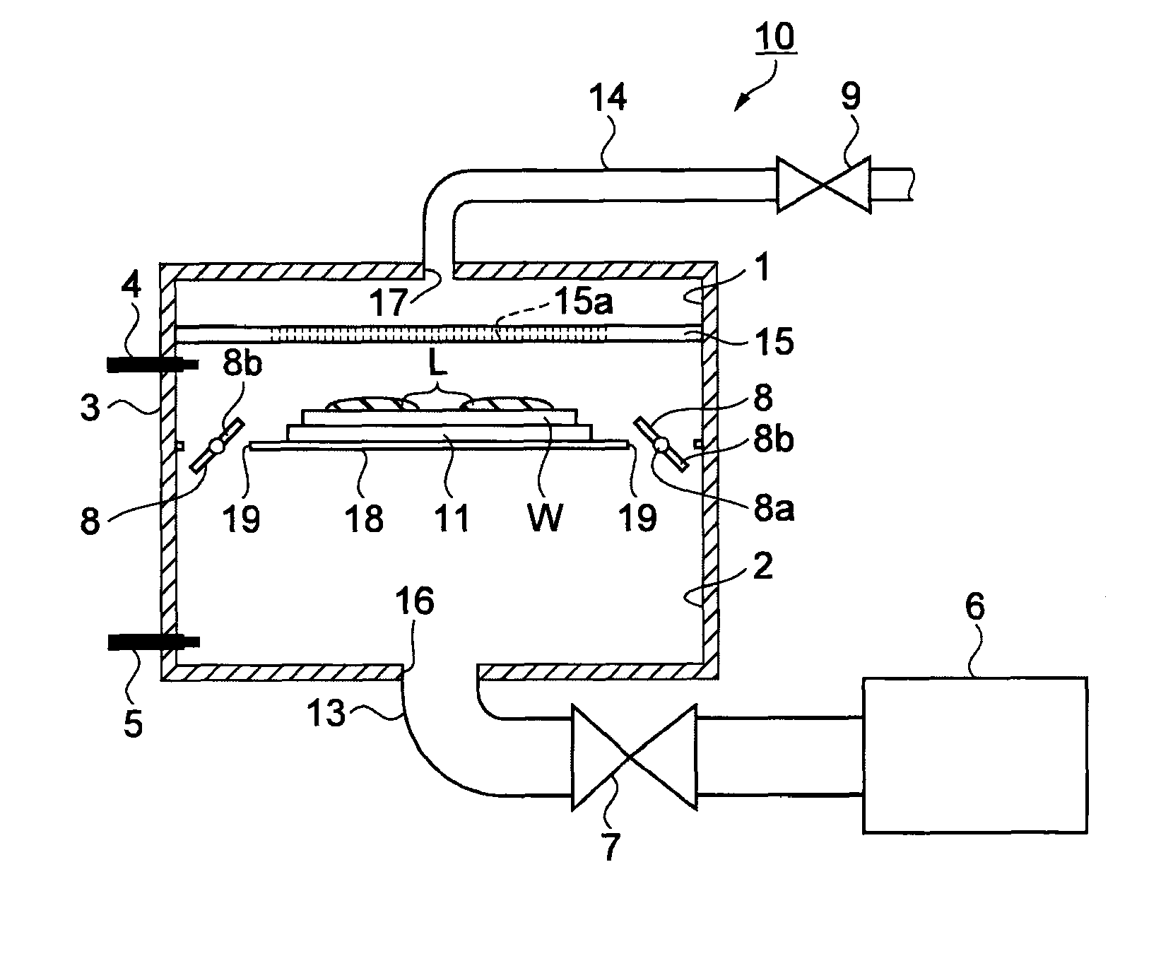
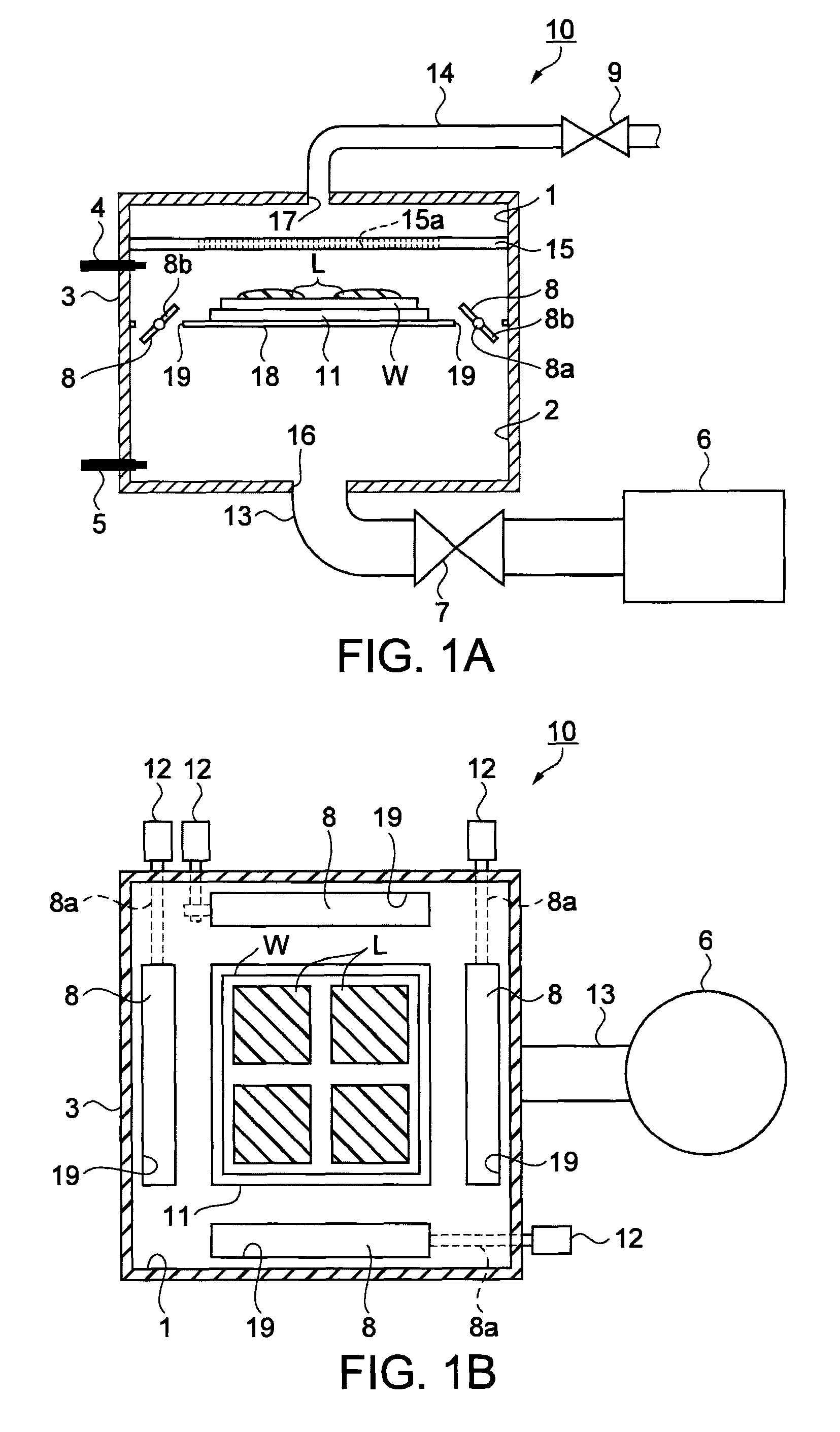
[0064]The reduced-pressure drying method according to the first embodiment applying the invention will now be explained with reference to FIGS. 3 and 4. FIG. 3 is a flowchart showing a reduced-pressure drying method according to the first embodiment of the invention. And, FIG. 4 is a graphical representation of the reduced-pressure drying profile of the reduced-pressure drying device. In detail, FIG. 4 is a graphical representation of the pressure change in the first and the second chambers 1, 2 with respect to the elapsed time of the reduced-pressure drying corresponding to the flowchart shown in FIG. 3. The vertical axis of the graph is a logarithmic axis representing the pressure P. Further, it shows an evaporation amount controlling type of reduced-pressure drying method performing the reduced-pressure drying by controlling the evaporation amount of the solvent evaporated from the liquid substance L.

[0065]Evaporation Amount Control Type of Reduced-Pressure Drying Method

[0066]As ...

second embodiment

[0086]A reduced-pressure drying method according to a second embodiment of the invention will now be explained with reference to FIGS. 6 and 7. FIG. 6 is a flowchart showing a reduced-pressure drying method according to the second embodiment of the invention. FIG. 7 is a graphical representation of the reduced-pressure drying profile of the reduced-pressure drying device. For details, FIG. 7 is a graphical representation of the pressure change in the first and the second chambers 1, 2 with respect to the elapsed time of the reduced-pressure drying corresponding to the flowchart shown in FIG. 6. The vertical axis of the graph is a logarithmic axis representing the pressure P. Further, it shows a shape-control type of reduced-pressure drying method for performing reduced-pressure drying while controlling the shape of the liquid substance L.

[0087]Shape Control Type of Reduced-Pressure Drying Method

[0088]As shown in FIG. 6, the reduced-pressure drying method according to the second embo...

third embodiment

[0100]A reduced-pressure drying method according to a third embodiment of the invention will now be explained with reference to FIGS. 8 and 9. FIG. 8 is a flowchart showing a reduced-pressure drying method according to the third embodiment of the invention. FIG. 9 is a graphical representation of the reduced-pressure drying profile of the reduced-pressure drying device. For details, FIG. 9 is a graphical representation of the pressure change in the first and the second chambers 1, 2 with respect to the elapsed time of the reduced-pressure drying corresponding to the flowchart shown in FIG. 8. Further, it shows a rapid drying type of reduced-pressure drying method.

[0101]Rapid Drying Type of Reduced-Pressure Drying Method

[0102]As shown in FIG. 8, the reduced-pressure drying method according to the third embodiment includes a decompressing step (step S21) for decompressing the second chamber 2 not communicated with the first chamber 1 housing the substrate W in a substantially airtight...


PUM

PropertyMeasurementUnit
thicknessaaaaaaaaaa
thicknessaaaaaaaaaa
thicknessaaaaaaaaaa

Abstract

A reduced-pressure drying method includes: decompressing a second chamber communicated with a first chamber housing a base material coated with a liquid substance containing a solvent to predetermined operative pressure by a decompressing device; leaving the first chamber closed in response to reaching the predetermined operative pressure until the evaporated solvent raising the pressure in the first chamber to predetermined pressure; communicating the first chamber with the pressure raised to the predetermined pressure with the second chamber; and discharging the vapor of the solvent dispersed in the first and the second chambers by the decompressing device.

Description

BACKGROUND OF THE INVENTION[0001]1. Technical Field[0002]The present invention relates to a reduced-pressure drying method for drying a base material coated with a liquid substance under reduced pressure to form a film on a surface of the base material, a method of manufacturing a functional film, a method of manufacturing an electro-optic device, an electro-optic device, a liquid crystal display device, an organic EL display device, and an electronic apparatus.[0003]2. Related Art[0004]A reduced-pressure drying method using a reduced-pressure drying device, which is used for forming a film on a surface of a wafer-like substrate (base material) made from, for example, semiconductor by applying a liquid substance including film forming material and is capable of drying the substrate by evaporating a fluxing material (solvent) included in the liquid substance under reduced pressure, is known. For example, in JP-A-2004-47797, there is proposed a reduced-pressure drying device provided ...

Claims


Application Information

Patent Timeline
Patent Type & Authority Patents(United States)
IPC IPC(8): G02F1/13G02F1/1337F26B21/06
CPCG02F1/1303H01L21/67034G02F1/133516Y10T428/10G02F1/1337G02F1/13363C09K2323/00
Inventor GOMI, KAZUHIRO
Owner SEIKO EPSON CORP
Why Eureka
Try Eureka