High frequency device with variable frequency and variable load impedance matching

a high frequency device and load impedance matching technology, applied in the direction of power conversion systems, dynamo-electric converter control, electric discharge tubes, etc., can solve the problems of not being able to match all load impedance zb>, not being able to make an optimal setting, and not being able to achieve the effect of reducing simple control operation, and lowering the reflected wave power

Active Publication Date: 2012-06-19
DAIHEN CORP
View PDF13 Cites 46 Cited by
  • Summary
  • Abstract
  • Description
  • Claims
  • Application Information

AI Technical Summary

Benefits of technology

[0024]The invention has been made in consideration of the above-mentioned problems, and its object is to provide the high frequency device using the variable frequency type high-frequency power supplier without using the auto impedance matcher and capable of decreasing the reflected wave power even when characteristics of the load thereof has a large variation in the load impedance Z1 throughout the entire manufacturing process.
[0029]a frequency control unit that controls the oscillation frequency of the oscillating unit so as to lower the reflected wave information;
[0041]a frequency control unit that controls the oscillation frequency of the oscillating unit so as to lower the reflected wave information;
[0043]an element control unit that controls any one of the two variable reactance elements of the impedance adjusting unit at a time so as to lower the reflected wave information.
[0050]According to the invention, even when the variable frequency type high-frequency power supplier is employed and an auto impedance matcher is not employed, it is possible to control both resistance component R and reactance component X of the load side impedance, and thus it is also possible to lower the reflected wave power. Moreover, adjustment of the resistance component R can be performed by a simple control operation. As a result, for example, throughout the entire manufacturing process, even when a load has characteristics that the load impedance Z1 greatly varies, it is possible to lower the reflected wave power. It may be also possible to perform the control operation so as to lower the absolute value of reflection coefficient.
[0051]In addition, even when two variable reactance elements are used, the number of variable reactance elements that can be controlled by the reactance element control circuit 19 at a time while the high frequency power is supplied to the load is one. Hence, it is comparatively easy to control the variable reactance element.

Problems solved by technology

However, in some cases the reflected wave power may not be sufficiently lowered only by controlling the output frequency of the high-frequency power supplier 50.
In addition, there is limitation in the range of reactance component X that is changed by changing the output frequency of the high-frequency power supplier 50, and thus it is not possible to match all load impedance Z1 only by controlling the output frequency of the high-frequency power supplier 50.
However, since the load impedance Z1 varies every moment, it is not possible to make an optimum setting for every time in a manufacturing process.
However, in the case where a load has characteristics in which the load impedance Z1 greatly varies throughout the entire manufacturing process, sometimes the reflected wave power may not be sufficiently lowered and may become more than the reference value when using such a high frequency device.
However, since the auto impedance matcher controls both of the resistance component R and the reactance component X, the control operation is complicated.
Moreover, when using the auto impedance matcher, size of the device and price thereof increase.
In addition, when using the auto impedance matcher, there is a possibility that the control operation is unstable since the matching operation by the auto impedance matcher and the adjusting operation of the output frequency by the high-frequency power supplier 50 are performed simultaneously.

Method used


Image

  • High frequency device with variable frequency and variable load impedance matching
  • High frequency device with variable frequency and variable load impedance matching
  • High frequency device with variable frequency and variable load impedance matching

Examples


first embodiment

[0060](First Embodiment)

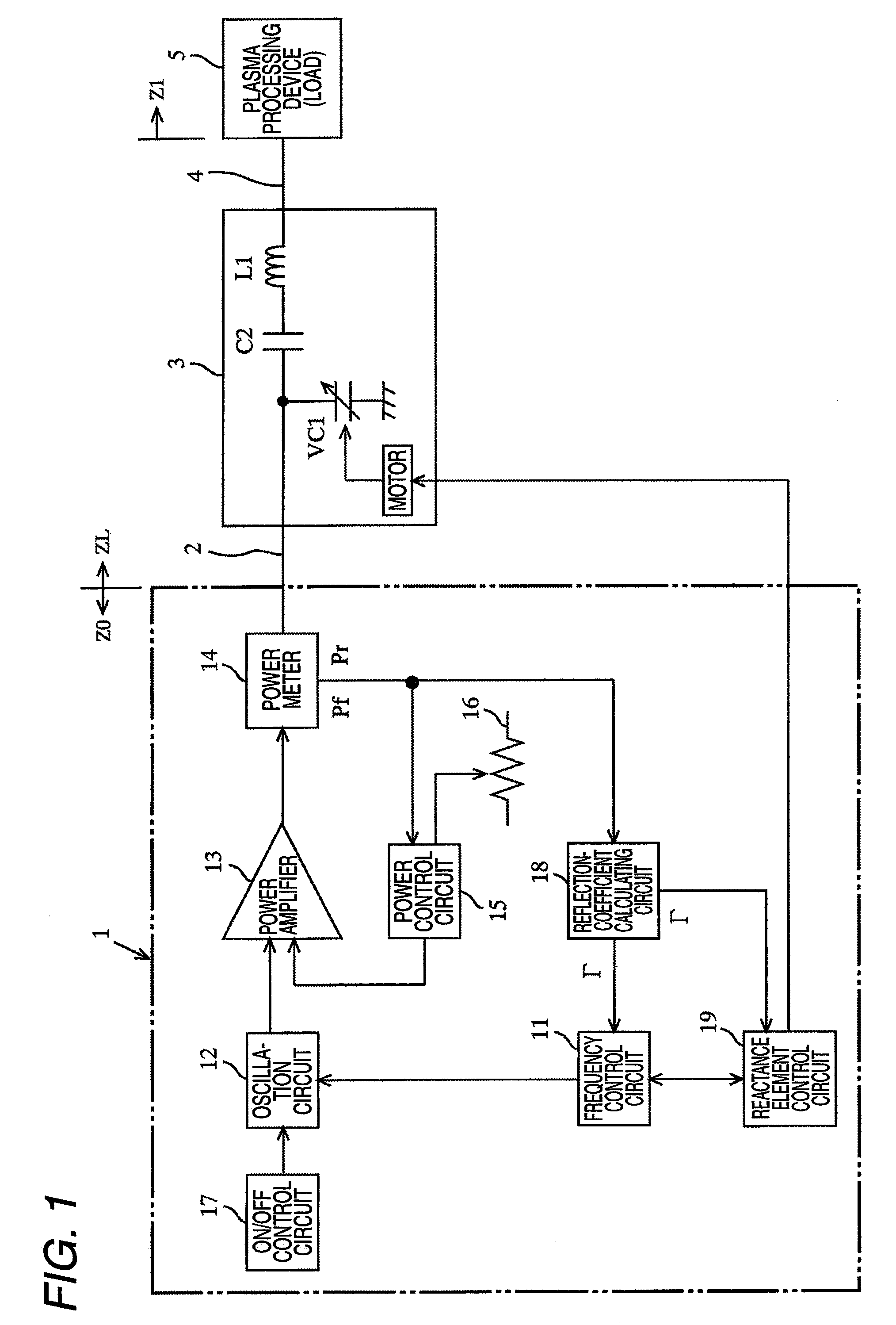
[0061]FIG. 1 is a diagram illustrating an exemplary configuration of a high frequency device according to a first embodiment of the invention and connection relation between the high frequency device and a load 5. The device including a high-frequency power supplier 1 and an impedance adjuster 3 disposed at a downstream of the high-frequency power supplier 1 in a power supplying direction is referred to as the high frequency device.

[0062]The high-frequency power supplier 1 is a system for supplying the load 5 with high frequency power generated by a power amplifier 13 that amplifies a high frequency signal output from an oscillation circuit 12. The high frequency power output from the high-frequency power supplier 1 is supplied to the load 5 through a transmission line 2 formed of a coaxial cable, an impedance adjuster 3, and a load connection portion 4 formed of a shielded copper plate. Generally, such a kind of the high-frequency power supplier 1 outputs hi...

second embodiment

[0100](Second Embodiment)

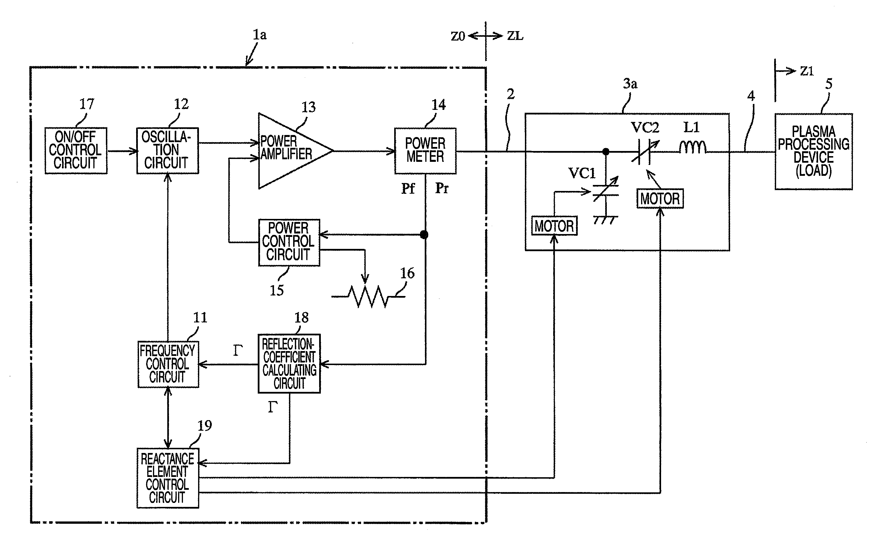
[0101]FIG. 4 is a diagram illustrating an exemplary configuration of a high frequency device according to a second embodiment of the invention and connection relation between the high frequency device and the load 5. Additionally, a device configured to combine a high-frequency power supplier 1a and an impedance adjuster 3a is referred to as a high frequency device.

[0102]In the impedance adjuster 3a shown in FIG. 4, the fixed capacitor C2 of the impedance adjuster 3 shown in FIG. 1 is changed into a variable capacitor VC2. The variable capacitor VC2, likewise the variable capacitor VC1, is configured to change capacitance thereof by using a motor. Additionally, the motor, likewise the variable capacitor VC1, is configured to be controlled by the reactance element control circuit 19.

[0103]The high-frequency power supplier 1a is mostly the same as the high-frequency power supplier 1 shown in FIG. 1 but is configured to change the capacitance of the variable ca...


PUM


Abstract

A high frequency device for supplying a high frequency power to a load, the high frequency device includes: an oscillating unit that can vary an oscillation frequency; a high frequency power supplying unit that serves as a power source by amplifying an oscillation signal output from the oscillating unit for supplying the high frequency power to the load; a reflected-wave information calculating unit that calculates reflected wave information on a reflected wave power, and outputs the reflected wave information; a frequency control unit that controls the oscillation frequency of the oscillating unit so as to lower the reflected wave information; an impedance adjusting unit that is disposed at a downstream of the high frequency power supplying unit in a power supplying direction, and that has at least one variable reactance element which can be controlled; and an element control unit that controls the variable reactance element of the impedance adjusting unit so as to lower the reflected wave information.

Description

BACKGROUND OF THE INVENTION[0001]1. Technical Field of the Invention[0002]The present invention relates to a high-frequency device for supplying power to a load, such as a plasma processing device that performs, for example, plasma etching and plasma CVD.[0003]2. Related Art[0004]In the load such as a plasma processing device that performs, for example, plasma etching and plasma CVD, an impedance of the load varies every moment in accordance with progress of a manufacturing process. In order to effectively supply power to the load, it is necessary to adjust an impedance (hereinafter, it is referred to as a load side impedance ZL) on the load side seen from an output terminal of the high-frequency power supplier in accordance with variation of the load impedance Z1 (an impedance corresponding to the load). Hence, generally, not only the high-frequency power supplier for supplying the high frequency power, but also an impedance adjuster for adjusting the load side impedance ZL is comb...

Claims


Application Information

Patent Timeline
Patent Type & Authority Patents(United States)
IPC IPC(8): H02M5/00H02P11/00
CPCH01J37/32091H01J37/32174H01J37/32183H03H7/40
Inventor OMAE, SHUJIMAEDA, KOSUKETANAKA, RYOHEIITO, HIDEO
Owner DAIHEN CORP
Why Eureka
Try Eureka