X-ray generating device

a generation device and x-ray technology, applied in the direction of x-ray tube targets, nuclear engineering, x-ray tubes, etc., can solve the problems of reducing the degree of vacuum inside the device, affecting the quality of x-ray radiation, so as to increase the beam diameter, increase the amount of x-ray radiation, and the size of the radiation source is very small.

Inactive Publication Date: 2012-06-26
CANON KK
View PDF3 Cites 39 Cited by
  • Summary
  • Abstract
  • Description
  • Claims
  • Application Information

AI Technical Summary

Benefits of technology

[0013]According to the present invention, the electron beams are individually focused on the targets and the generated X-rays are added together, so that the total amount of X-ray radiation can be increased while limiting the current of the electron beam that is incident per target. Therefore, the target does not easily melt, whereby the size of the radiation source can be made very small while increasing the amount of X-ray radiation. Moreover, by limiting the current of the electron beam per target, an increase in the beam diameter due to repulsion between charges of electrons can be suppressed, whereby the size of radiation source can be further reduced.

Problems solved by technology

However, in existing microfocus X-ray generating devices, when a high current electron beam is made incident on a very small focal spot, a target can be damaged and various adverse effects, such as a decrease in the degree of vacuum inside the device, are produced.
Therefore, it is difficult to reduce the size of the radiation source while increasing the amount of X-ray radiation.
As a result, it is difficult to reduce the size of the radiation source.
Also in this respect, it is difficult to reduce the size of radiation source while increasing the amount of X-ray radiation.

Method used


Image

  • X-ray generating device
  • X-ray generating device
  • X-ray generating device

Examples


first embodiment

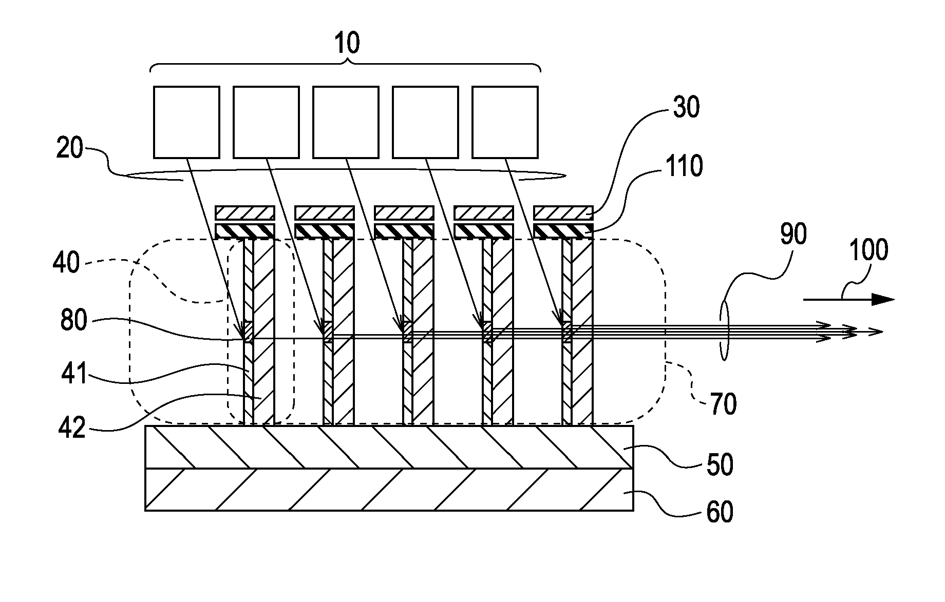
[0025]FIGS. 1A and 1B are schematic views of an X-ray generating device according to a first embodiment of the present invention. The main structures of the X-ray generating device illustrated in FIGS. 1A and 1B are the same except that X-rays are output in different directions. Therefore, the following description will be limited to the X-ray generating device illustrated in FIG. 1A. The X-ray generating device according to the first embodiment includes at least one electron-beam generator 10 (or a plurality thereof) that generates electron beams 20, a target assembly group 70 that generates X-rays from the electron beams 20, and electron lenses 30 that are disposed between the electron-beam generator 10 and the target assembly group 70. The electron lenses 30 serve as an electron-beam focusing unit that focuses the electron beams 20 onto focal spots having an appropriate size.

[0026]As illustrated in FIG. 1A, the target assembly group 70 includes target assemblies 40 that are arran...

second embodiment

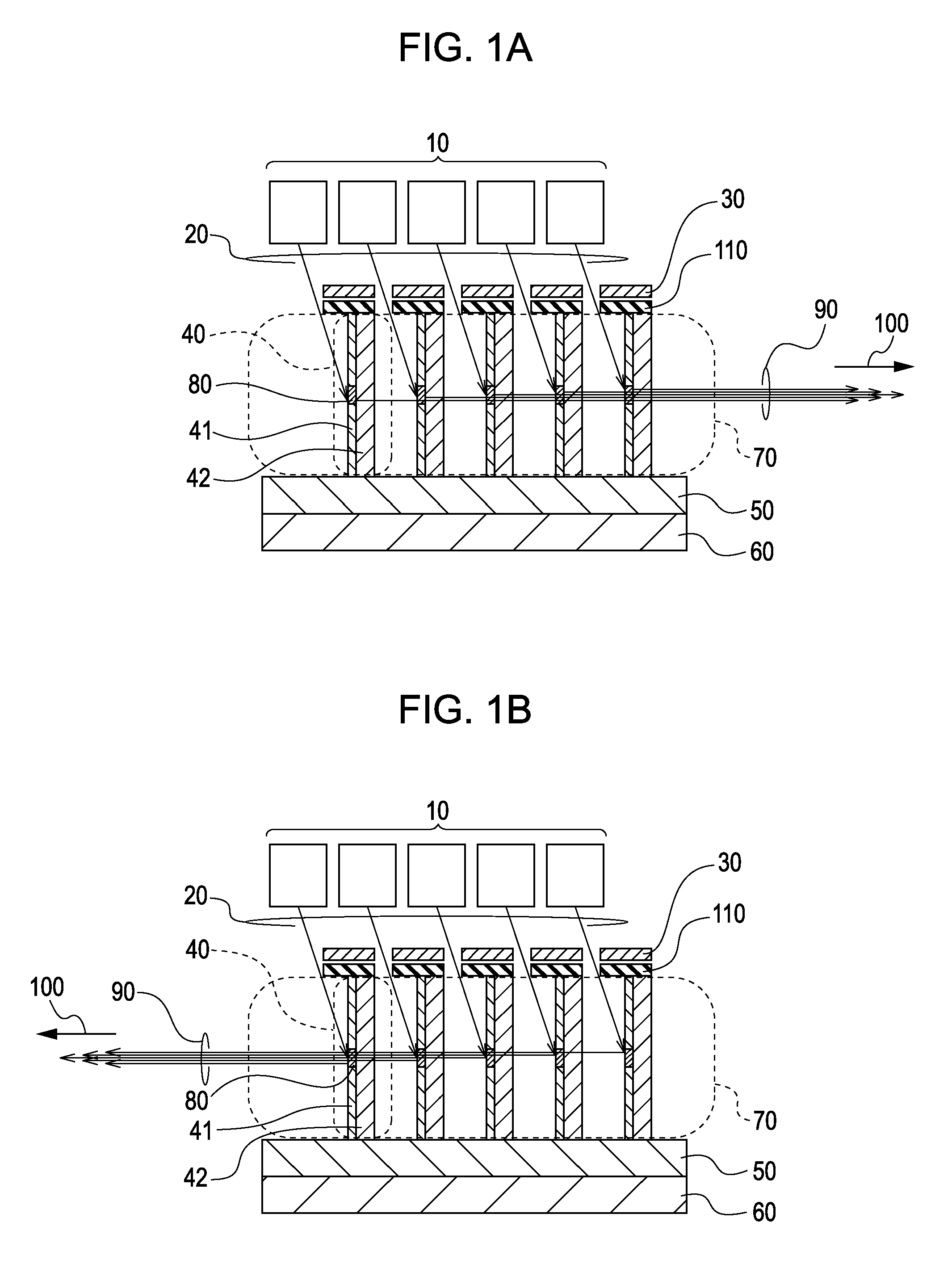
[0038]FIGS. 6A and 6B are schematic views of an X-ray generating device according to a second embodiment of the present invention. Embodiments illustrated in FIGS. 6A and 6B are the same except that X-rays 90 are output in a first direction 100 (to the right) in the case of FIG. 6A and in a second direction 100 (to the left) in the case of FIG. 6B. Accordingly, only the case of FIG. 6A will be mainly described below. The second embodiment differs from the first embodiment mainly in that electron-beam generators 10 and electron lenses 30 are integrated in target assemblies 40. In the first and second embodiments like reference numbers generally indicate identical, structurally similar or functionally similar elements.

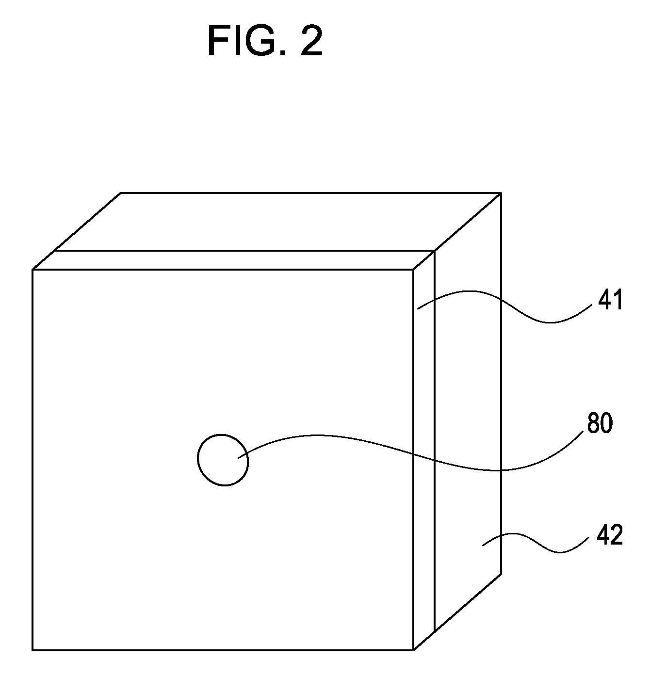
[0039]FIG. 7 is a schematic view of the target assembly 40 in the second embodiment. The target assembly 40 includes a target 41 disposed on a side of a supporting member 42. The target 41, for example, may cover all of the side of the supporting member 42 as in the case...

example 1

[0050]Next, a first example of the X-ray generating device according to the first embodiment of the present invention will be described. To be specific, an example of making the X-ray generating device illustrated in FIG. 1A, which is suitable for a case in which electrons are accelerated to 60 keV and collide with a molybdenum target, will be described.

[0051]First, the target assembly 40 was fabricated. The average penetration depth Y of an electron beam of 60 keV into molybdenum is about 5 μm. As the target 41, a molybdenum thin film having a thickness of 5 μm was formed on a silicon wafer by electron beam deposition. The silicon wafer, which served as the supporting member 42, was a double-side polished silicon wafer having a diameter of 4 inches and a thickness of 200 μm. Subsequently, the target assemblies 40 were made by cutting the silicon wafer with a dicing saw into segments each measuring 10 mm per side. The target 41 can be formed on the supporting member 42 by photolitho...


PUM


Abstract

An X-ray generating device includes an electron-beam generator, a target assembly group, and an electron-beam focusing unit. The electron-beam generator generates electron beams. The target assembly group includes a plurality of target assemblies that are arranged along a straight line in a direction in which X-rays are output; each of the target assemblies includes a target and a supporting member; the target generates X-rays from one of the electron beams generated by the electron-beam generator; and the supporting member supports the target by being disposed adjacent thereto. The electron-beam focusing unit focuses the electron beams onto the targets included in the target assembly group so that X-rays are generated in each of the target assemblies and output along the straight line after passing through the target assemblies.

Description

BACKGROUND OF THE INVENTION[0001]1. Field of the Invention[0002]The present invention relates to a microfocus X-ray generating device that is used for non-destructive X-ray imaging in the industrial field and for diagnostic applications in the medical field.[0003]2. Description of the Related Art[0004]It is known that X-rays are used for non-destructive testing in the industrial field and for radiography in the medical field because the internal structure of an object can be observed by utilizing the high penetrability of X-rays.[0005]The resolution of an X-ray radiography depends, among other things, on the size of the radiation source of X-rays. Therefore, in order to observe a very small internal structure, a microfocus X-ray generating device that has a very small radiation source needs to be used.[0006]In order to increase the brightness of an X-ray radiograph, the amount of X-ray radiation needs to be increased.[0007]Traditionally, the amount of X-ray radiation has been increa...

Claims


Application Information

Patent Timeline
Patent Type & Authority Patents(United States)
IPC IPC(8): H01J35/00
CPCH01J35/06H01J35/08H01J2235/068H01J2235/087H01J2235/088H01J2235/1204H01J35/116
Inventor SATO, GENTA
Owner CANON KK
Why Eureka
Try Eureka