
Modeling data creating system, manufacturing method, and modeling data creating program

a modeling data and creating system technology, applied in the direction of additive manufacturing processes, instruments, manufacturing tools, etc., can solve the problems of model distortion, distortion of model, and often a degree that cannot be corrected, and achieve the effect of suppressing distortion of structure such as bowing, accurate formation and precise forming

Active Publication Date: 2012-06-26
SHOFU INC
View PDF35 Cites 17 Cited by
  • Summary
  • Abstract
  • Description
  • Claims
  • Application Information

AI Technical Summary

Benefits of technology

The present invention provides a system and method for creating modeling data for a structure that is resistant to deformations during the forming and sintering processes. This modeling data is useful for creating complex structures such as crowns and bridges that require precise forming. The system includes a composition data recording unit that records the composition of the material used in the model, a change amount data recording unit that records the amount of change in the material due to drying, polymerization, and sintering, a correction unit that uses the change amount data to correct the structure data so that the model formed matches the desired form, a contour generation unit that generates contour data expressing the shape of the space between the structure and a projection plane, and a support member generation unit that generates support member data to fill the space between the structure and a base plane. The model is supported in its entirety by the support member, preventing distortions and bowing during the formation process. The system can provide modeling data that is resistant to deformation and accurately reflects the desired form.

Problems solved by technology

However, when a model formed by the abovementioned layered modeling apparatus is applied to the frame of a prosthesis or the like, it is necessary to perform a sintering process following the modeling, and there have thus been many situations where the model sags or collapses under its own weight or due to the atmosphere within the kiln as the temperature rises, thereby taking on a different shape than was originally intended.
In particular, when firing a long model, such as a long-span bridge frame, distortions often occur to a degree that cannot be corrected.
Meanwhile, even if a model is formed from a material that does not require firing, there are cases where the model distorts due to drying during shaping, polymerization, and so on.
In addition, because frames for dental prostheses and the like are often designed to be applied and luted to the patient's anchor teeth using a material such as a cement, there are many situations where there is space between the frame and the modeling table.

Method used


Image

  • Modeling data creating system, manufacturing method, and modeling data creating program
  • Modeling data creating system, manufacturing method, and modeling data creating program
  • Modeling data creating system, manufacturing method, and modeling data creating program

Examples


embodiment 1

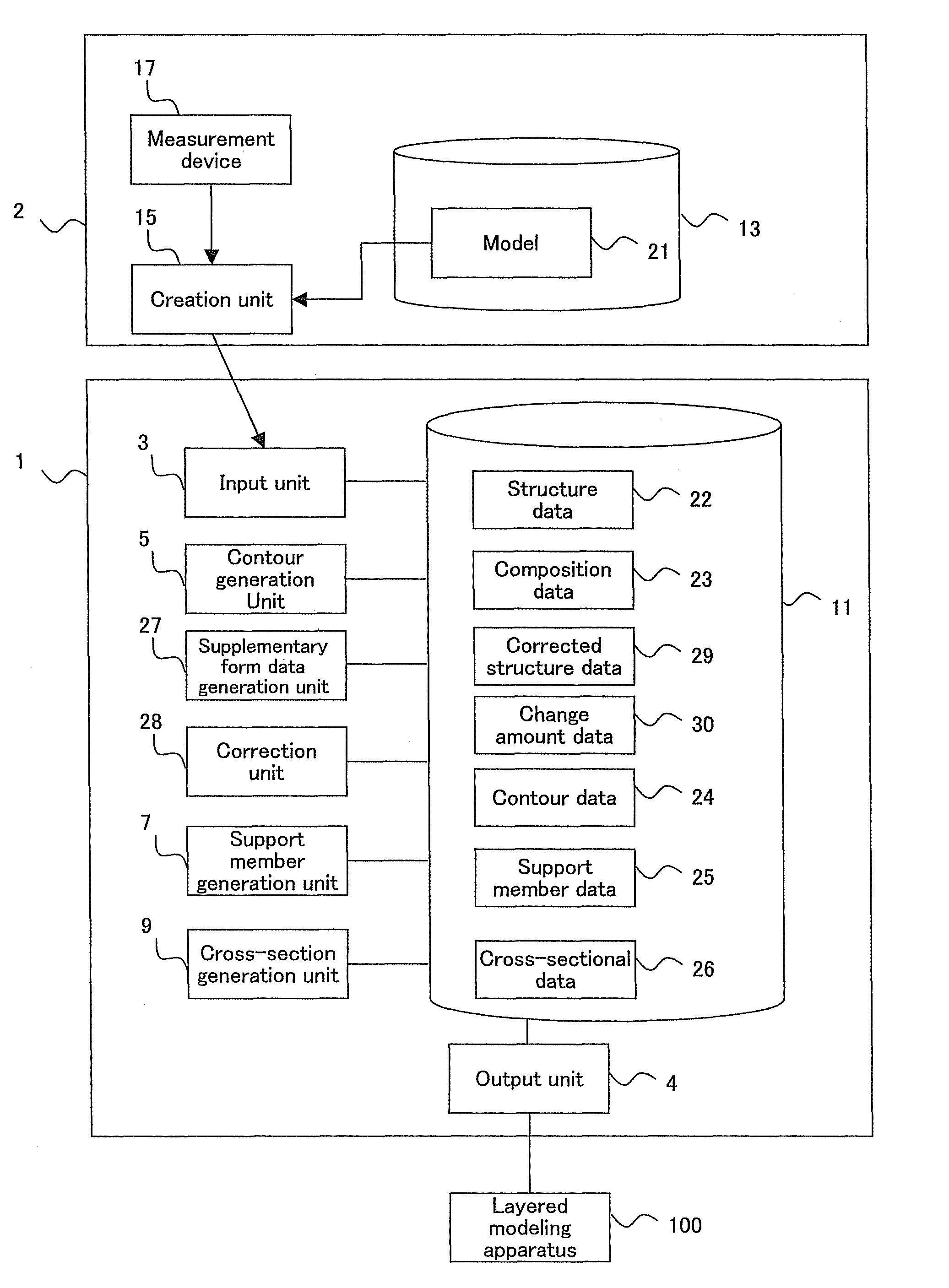
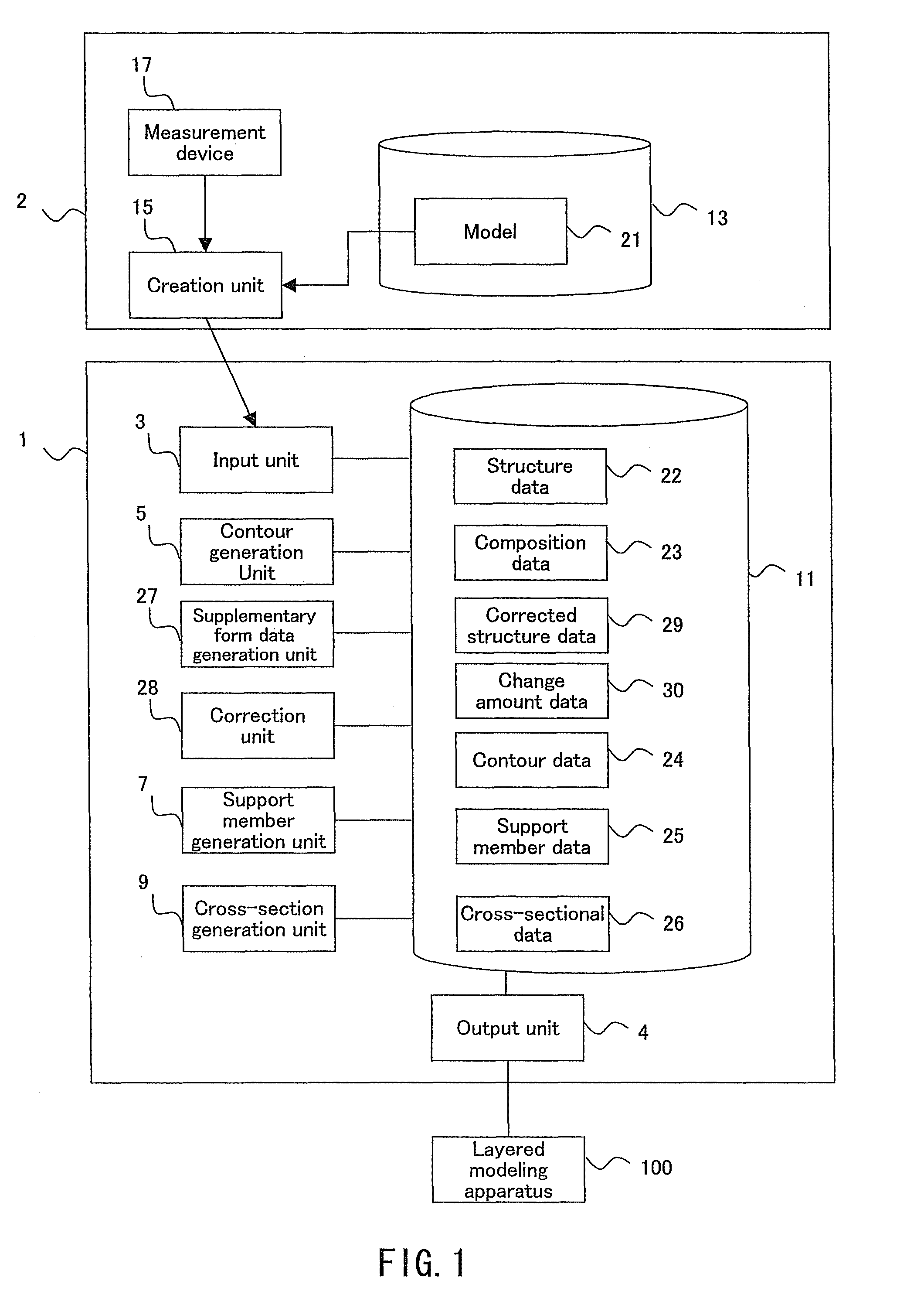
[0097]Embodiment 1 relates to a modeling data creating system that creates data expressing the form of a model formed by layering a powder upon a modeling table. The present embodiment describes an example where a layered modeling apparatus manufactures, for example, a zirconia structure, used as a bridge frame for a porcelain fused to metal restoration, as a model. FIG. 1 is a functional block diagram illustrating the configuration of the modeling data creating system according to Embodiment 1.

[0098]As shown in FIG. 1, a modeling data creating system 1 includes an input unit 3, an output unit 4, a supplementary form data generation unit 27, a correction unit 28, a contour generation unit 5, a support member generation unit 7, a cross-section generation unit 9, and a recording unit 11. The modeling data creating system 1 is connected to a prosthesis form data creation system 2 and a layered modeling apparatus 100.

[0099]The prosthesis form data creation system 2 includes a measuring ...

embodiment 2

[0212]Embodiment 2 relates to a manufacturing method for manufacturing a structure such as a frame using the cross-sectional data 26 created by the modeling data creating system 1 of Embodiment 1 and the layered modeling apparatus 100. The layered modeling apparatus 100 is an apparatus that creates a desired model by layering, on a modeling table, modeling layers in which parts of the layers are selectively shaped.

[0213]FIG. 17 is a perspective view illustrating the general configuration of the layered modeling apparatus 100. In FIG. 17, the horizontal axes orthogonal to each other are taken as the X and Y axes, whereas the vertical axis is taken as the Z axis. As shown in FIG. 17, the layered modeling apparatus 100 includes a modeling table 110, a housing 120, a powder feeder 130, a solution feeder 140, a scraper member 150, and a light source 160. In FIG. 11, to make the construction easier to understand, the housing 120 is indicated by a double-dot-dash line, so that the modeling...


PUM

PropertyMeasurementUnit
anglesaaaaaaaaaa
compositionaaaaaaaaaa
structureaaaaaaaaaa

Abstract

A modeling data creating system comprises: a correction unit that corrects structure data expressing the form of a desired structure based on change amount data; a contour generation unit that generates contour data expressing the contour of a support member for supporting the structure on a modeling table, based on the structure data; a support member generation unit that generates support member data expressing the form of multiple column bodies within the contour expressed by the contour data; and a cross-section generation unit that generates cross-sectional data expressing the cross-sectional shape of each of multiple planes approximately parallel to the modeling table, the planes making up a model configured of the support member expressed by the support member data and the structure expressed by the structure data. Through this, the modeling data creating system suppresses a difference in the model that is to be formed and the modeling data expressing the form of the model.

Description

CROSS-REFERENCE TO RELATED APPLICATIONS[0001]This application claims the benefit of PCT International Patent Application No. PCT / JP2007 / 069723, filed Oct. 10, 2007, and Japanese Patent Application No. 2006-276201, filed Oct. 10, 2006, in the Japanese Patent Office, the disclosures of which are incorporated herein by reference.BACKGROUND OF THE INVENTION[0002]1. Field of the Invention[0003]The present invention relates to a modeling data creating system that creates data used by a layered modeling apparatus that forms a model by layering modeling layers, parts of which have been selectively shaped, on a base plane.[0004]2. Description of the Related Art[0005]With prostheses such as crowns, bridges, inlays, onlays, or implants used in prosthetic treatments for the purpose of restoring facial, masticatory, pronunciation, or vocalization functionality to patients, there is a demand for the devices to maintain a high degree of strength and durability within the oral cavity for a long per...

Claims


Application Information

Patent Timeline
Patent Type & Authority Patents(United States)
IPC IPC(8): G06F19/00A61C13/003A61C13/007A61C13/08A61C13/15B29C67/00G16Z99/00
CPCA61C13/0004B29C67/0077B29C67/0092B29C64/153B29C64/40B33Y50/02A61C5/77G16Z99/00B33Y50/00G16H20/40
Inventor INOUE, TOMOYUKI
Owner SHOFU INC
Learn More