Modified crown reduction gear

a technology of reduction gear and crown, which is applied in the direction of belt/chain/gearing, toothed gearing, belt/chain/gearing, etc., can solve the problems of increasing weight, increasing the number of teeth, and increasing the weight of the whole mechanism, so as to reduce the effect of reducing the accuracy of workpiece precision and reducing the burden of manufacturing accuracy and assembling

Active Publication Date: 2012-07-03
FUKUSHIMA UNIVERSITY
View PDF12 Cites 10 Cited by
  • Summary
  • Abstract
  • Description
  • Claims
  • Application Information

AI Technical Summary

Benefits of technology

[0008]The present invention has been made to solve the afore-mentioned problems, and an object of the present invention is to provide a reduction gear capable of satisfying, at high level, each of: realizing a high reduction ratio; preventing backlash by securing rotation smoothness; and carrying out compactification and weight saving of its entire mechanism.
[0010]In the modified crown reduction gear of the invention, since the difference in teeth number between the movable and fixed crown gears 1 and 2 is one, a high reduction ratio can be realized. In addition, rotation smoothness is secured and backlash is prevented from occurring because the engaging positions of the movable and fixed crown gears 1 and 2 are dispersed at two places of both sides between which the gradient center line intervenes. Moreover, the movable and fixed crown gears 1 and 2 are combined so that their teeth are engaged with each other, and accordingly size in the axial direction can be compacted in particular. As a large starting torque is not required, it is not necessary to use a large motor in order to drive and rotate the pressing mechanism 16. Therefore, the entire mechanism is compacted and the weight is saved. That is, in the modified crown reduction gear of the invention, realizing a high reduction ratio, preventing backlash by securing rotation smoothness, and carrying out compactification and weight saving of the entire mechanism are simultaneously satisfied.
[0011]In the modified crown reduction gear of the invention, it is desirable that the pressing mechanism 16 is attached to an input axis 6 so as to be driven together in a rotation direction; and the movable crown gear 1 and the output axis 3 are driven by reduction rotation in association with the rotation of combination of the input axis 6 and the pressing mechanism 16. Thereby, the movable crown gear 1 pressed on the fixed crown gear 2 with the pressing mechanism 16, per se, performs precession movement by simply driving and rotating the pressing mechanism 16 coupled to the input axis 6. The rotation is transmitted to the output axis 3. Therefore, the entire mechanism is compacted and also burden of manufacturing accuracy and assembling is reduced.
[0012]Preferably, the pressing mechanism 16 is configured so that it can oscillate with respect to the input axis 6 in the direction of an axis. Thereby, precision error of workpiece or the like can be absorbed by the oscillation of the pressing mechanism 16, and burden of manufacturing accuracy and assembling is further reduced.
[0013]It is desirable that the pressing mechanism 16 comprises: a pressing axis 7 which is attached to the input axis 6 to rotate together; an arm 8 extended radially from the pressing axis 7; and a pressing member 17 which is mounted on a tip of the arm 8 to press the back face of the movable crown gear 1. Thereby, each gravity center of components can be placed on the same axis as much as possible, and oscillation can be reduced. The size in the axial direction is compacted and the weight of the whole mechanism is saved.
[0015]In the modified crown reduction gear of the invention, it is diserable that both or either of the fixed and movable crown gears 2 and 1 is made of flexible material. Thereby, the number of teeth engaging with each other at the two places of both sides is increased, and the rotation is further smoothed, so that lower oscillation and lower backlash can be realized.

Problems solved by technology

Therefore, there is a problem that a reduction ratio is 2 / N (N: teeth number) at most.
In the harmonic drive reduction gear, there are issues that a large motor is required and thereby the whole mechanism grows in size and also causes weight increase, because a starting torque of gears also becomes large.
However, as the bevel gears are placed in contact at one place, there is a problem that rotation smoothness is reduced and backlash tends to take place.
There are issues that the size in the axial direction is increased and thereby the whole mechanism grows in size and also causes weight increase, because the bevel gears are also combined with each other.
That is, the known harmonic drive or oscillating bevel reduction gear has difficulty in simultaneous pursuit of realizing a high reduction ratio, preventing backlash by rotation smoothness, compacting its entire mechanism and saving weight.
Therefore, they are not suitable to be embedded in a knuckle of a robot hand or the like.

Method used


Image

  • Modified crown reduction gear
  • Modified crown reduction gear
  • Modified crown reduction gear

Examples


Embodiment Construction

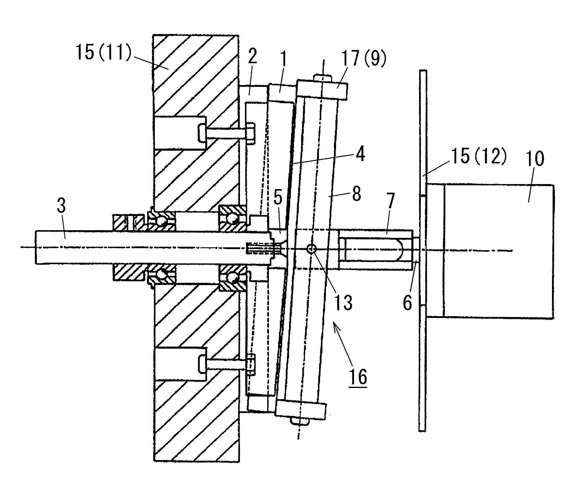
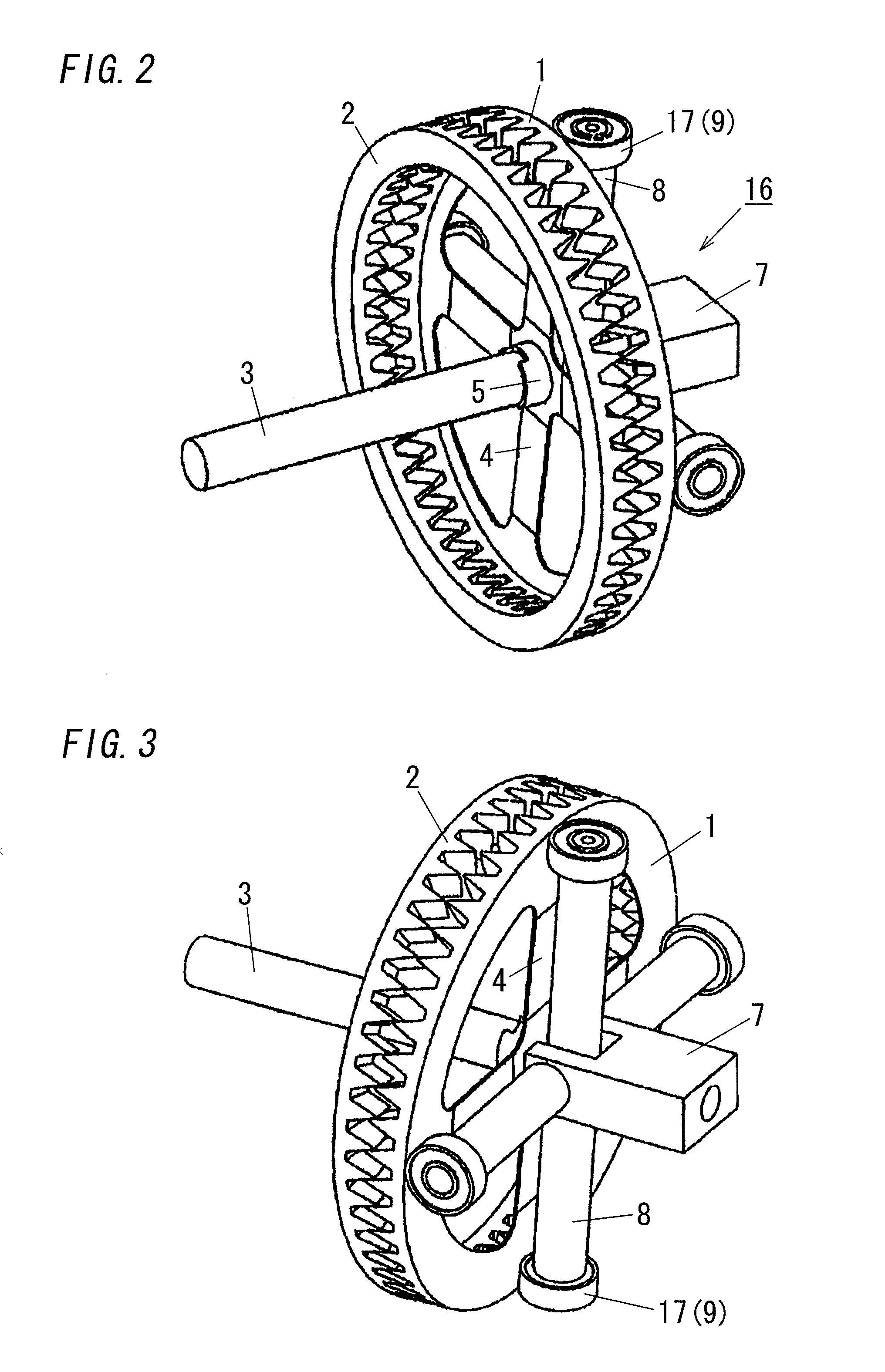
[0030]The present invention will be explained based on the embodiments shown in the accompanying drawings. FIGS. 1-3 show a modified crown reduction gear in accordance with an embodiment of the present invention.

[0031]As shown in FIG. 1, an external member 15 on which the modified crown reduction gear is placed is formed of an anterior wall 11 and a posterior wall 12 which face in parallel to each other at a predetermined distance apart. A fixed crown gear 2 is fixed on the face of the anterior wall 11 facing the posterior wall 12, and a movable crown gear 1 is engaged with the fixed crown gear 2 at a slant. The fixed and movable crown gears 2 and 1 have the same external diameter as each other, while the difference in teeth number between them is set to one. Accordingly, if the movable crown gear 1 is pressed on the fixed crown gear 2 with a pressing mechanism 16 to be described, the teeth of the crown gears 1 and 2 are not exactly engaged with one another and an inclined state ine...


PUM


Abstract

A reduction gear capable of satisfying, at high level, each of: realizing a high reduction ratio; preventing backlash by securing rotation smoothness; and carrying out compactification and weight saving of entire mechanism is provided. The reduction gear of the invention is a modified crown reduction gear, comprising: a pressing mechanism 16 operated to rotate; a fixed crown gear 2 fixed to an external member 15; a movable crown gear 1, wherein the difference in the number of teeth between the gears is one; and an output axis 3 flexibly attached to the gear 1. The gear 1 engages with the gear 2 at a slant by pressing-force provided from the mechanism 16. In this instance, contact locations of teeth of the gears 1 and 2 are dispersed at two places existing at both sides between which a gradient center line intervenes.

Description

TECHNICAL FIELD[0001]The invention relates to a mechanical reduction gear capable of realizing a large reduction ratio.BACKGROUND ART[0002]Harmonic drive reduction gears and oscillating bevel reduction gears are well known as reduction gears capable of realizing a large reduction ratio.[0003]The former, i.e., the harmonic drive reduction gear has a circular spline and a Flexspline which is two less in teeth number than the circular spline. The gear is a mechanism which continuously bends the Flexspline with a wave generator and thereby the Flexspline and the circular spline are engaged at two places (see Japanese Patent Application Publication Number 7 (1995)-103291).[0004]The harmonic drive reduction gear has advantages of prevention of occurrence of backlash and smooth rotation by the engagement at the two places. However, the difference in teeth number needs to be set to an even number equal to or more than two from construction condition. Therefore, there is a problem that a red...

Claims


Application Information

Patent Timeline
Patent Type & Authority Patents(United States)
IPC IPC(8): F16H35/00F16H23/00
CPCF16H1/321Y10T74/19614Y10T74/19
Inventor TAKAHASHI, TAKAYUKISASAKI, HIROYUKIMASUYAMA, TOMOYA
Owner FUKUSHIMA UNIVERSITY
Why Eureka
Try Eureka