
Tension fixation system

a technology of fixation system and tension, which is applied in the field of spinal disorders, can solve the problems of loss of mechanical integrity of the spine, deformation, neurological injury, etc., and achieve the effects of improving patient care, reducing spine deformation, and improving us

Active Publication Date: 2012-07-03
MASS MODULAR SPINE SYST
View PDF12 Cites 8 Cited by
  • Summary
  • Abstract
  • Description
  • Claims
  • Application Information

AI Technical Summary

Benefits of technology

"The present invention provides a way to attach a bone anchor to a structural member used for spinal fixation. This helps to correct spinal deformities and provide stability to the spine, allowing the load to be carried through the structural member. The invention uses a tensile loading component to attach the bone anchor to the structural member. It can be used with different types of bone anchors and structural members, and can reduce spinal deformity without the need for additional reduction instrumentation. It also allows for fixation in the absence of deformity."

Problems solved by technology

Failure of any structural components of the spine as a result of disease or injury may lead to loss of the mechanical integrity of the spine, which may lead to neurological injury, mechanical instability, and deformity.
Ultimately, this can lead to pain, loss of function, and / or neurological impairment.
Early constructs were generally limited to bone anchor fixation points at the ends of the structural member.
However, these constructs were limited in their ability to correct deformity as they were limited by the amount of force and moment, which could be imparted to the spine though a single bone anchor at the end of a structural member.
This limitation gave rise to segmental fixation systems, which allow larger corrective forces and moments to be applied to the spine because of multiple points of spine fixation through the use of multiple bone anchors.
While these reduction instrumentation systems may be used to good effect, they are space occupying, commonly cumbersome, and frequently time consuming in the confines of a surgical wound. which is already filled with the bone anchors and the structural members.
Their use often leads to both increased wound size and operative time, which translate to potential increased operative morbidity given increased risks of prolonged anesthesia, bleeding, and infection.
While these techniques offer some advantages over reduction instrumentation techniques and are still used on a limited basis, they have lost favor for reasons of neurological risk associated with passing sub-laminar wires and issues concerning secure fixation to the structural member.
This relatively severe limitation generally requires that a single long posted screw anchor be solely loaded at the reduction of deformity, which increases the risk of failure of both the reduction and the anchor.

Method used


Image

  • Tension fixation system
  • Tension fixation system
  • Tension fixation system

Examples


Embodiment Construction

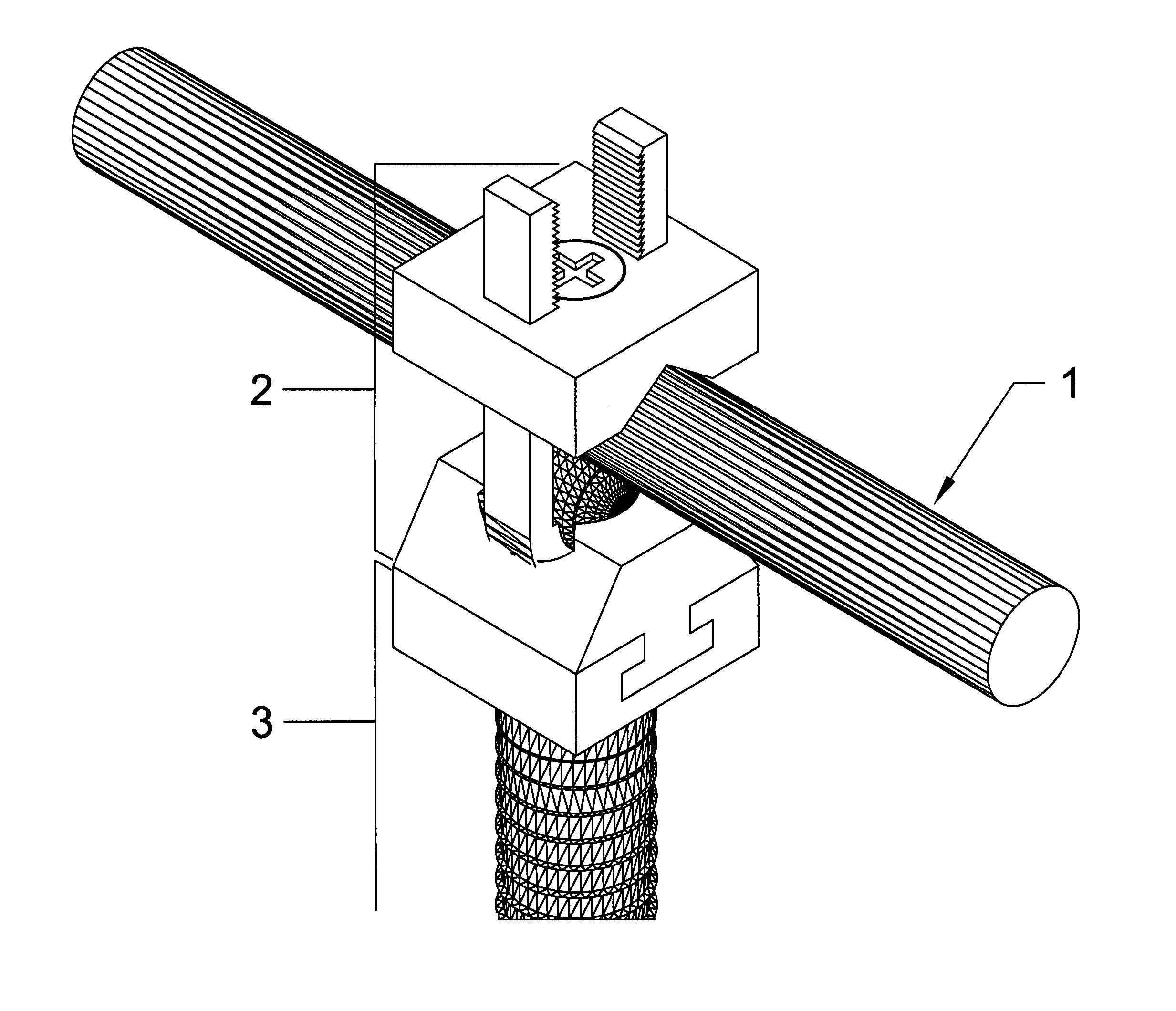
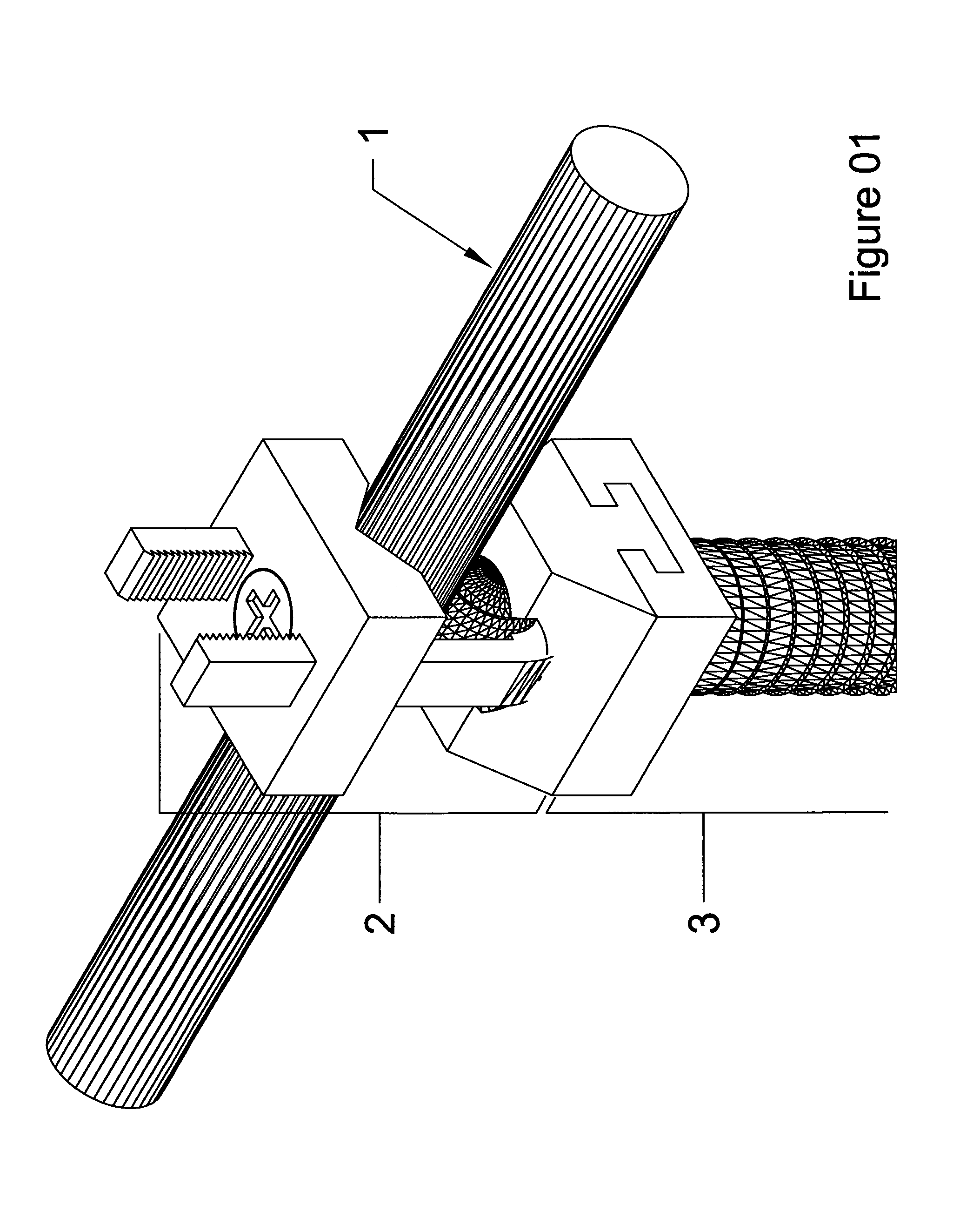
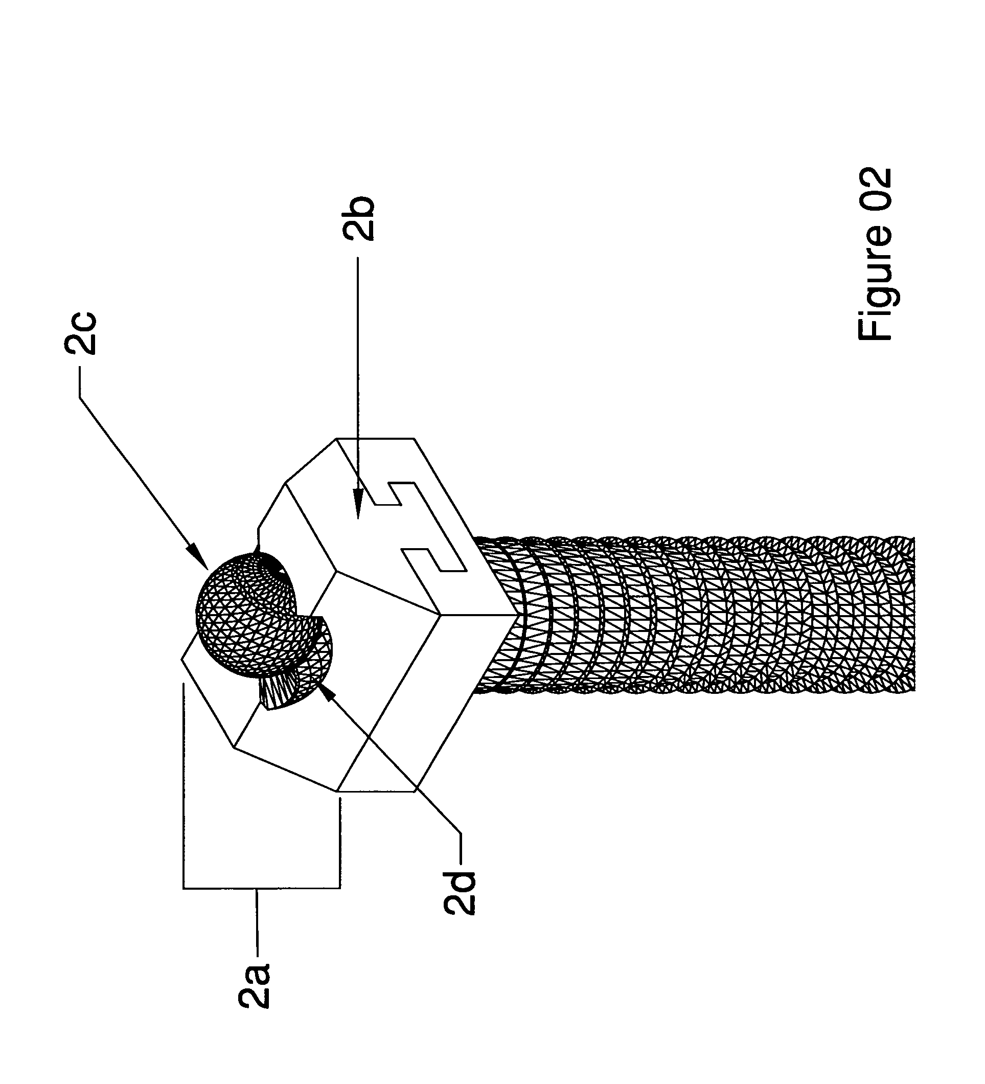
[0029]The present invention provides an apparatus and method for fixation of a bone anchor to the structural member of a spine fixation system whereby the spine is provided mechanical stability and correction of deformity through load carried fully or partially through the structural member. This invention provides fixation of a bone anchor to a structural member through tensile loading of a component of the fixation mechanism. This invention is widely adaptable to a variety of bone anchors and structural members. This invention allows reduction of spine deformity resulting from varied spinal disease through the fixation mechanism alone without the need for added reduction instrumentation systems. This invention equally provides a fixation mechanism for fixation of a bone anchor to the structural member of a spine fixation system in the absence of deformity.

[0030]In a general sense, the invention provides an apparatus for fixation of a bone anchor of a spinal fixation system to a su...


PUM


Abstract

The present invention provides an apparatus and method for fixation of a bone anchor to a structural member used for spinal fixation, whereby spinal deformity can be corrected and mechanical stability of the spine is provided so that load is carried fully or partially through the structural member. This invention provides fixation of a bone anchor to a structural member through tensile loading of a component of the fixation mechanism. This invention is widely adaptable to a variety of bone anchors and structural members. This invention allows reduction of spine deformity resulting from varied spinal disease through the fixation mechanism alone without the need for added reduction instrumentation systems. This invention equally provides a fixation mechanism for fixation of a bone anchor to the structural member of a spine fixation system in the absence of deformity.

Description

BACKGROUND OF THE INVENTION[0001]1. Field of the Invention[0002]The invention relates to apparatus and methods for treating spinal disorders. More particularly, the invention relates to spinal fixation systems.[0003]2. Summary of the Related Art[0004]The human spine is a system of articulated vertebral segments with tissues including vertebrae, intervertebral discs, facet joints, ligaments, and muscles. The human spine generally includes 24 vertebrae and the sacrum. These 24 vertebrae are designated from the head to the pelvis (cervical, thoracic, lumbar, and sacral). There are 7 cervical vertebrae, 12 thoracic vertebrae, 5 lumbar vertebrae (although this number may vary from 4 to 6 lumbar vertebrae in some humans), and 4 sacral vertebrae. The spine generally includes 25 articulations; each bone articulates with the one above and below. The superior C1 vertebra articulates with the skull and the inferior L5 vertebra articulates with the sacrum. With two exceptions, articulations bet...

Claims


Application Information

Patent Timeline
Patent Type & Authority Patents(United States)
IPC IPC(8): A61B17/70
CPCA61B17/7032A61B17/7037A61B17/7038
Inventor SNYDER, BRIAN D.VRESILOVIC, EDWARD J.MEHTA, HEMAL P.MULLER, JOHN A.
Owner MASS MODULAR SPINE SYST
Learn More