Delivery device for deposition

a delivery device and deposition technology, applied in the field of diffusing flow, can solve the problems of large amount of chemical vapor deposition reaction, difficult to avoid some direct reaction of different precursors, and relatively insensitive to transport non-uniformities

Active Publication Date: 2012-07-03
EASTMAN KODAK CO
View PDF44 Cites 23 Cited by
  • Summary
  • Abstract
  • Description
  • Claims
  • Application Information

AI Technical Summary

Benefits of technology

[0055]It is an advantage of the present invention that it can provide a compact apparatus for atomic layer deposition onto a substrate that is well suited to a number of different types of substrates and deposition environments.
[0056]It is a further advantage of the present invention that it allows operation, in preferred embodiments, under atmospheric pressure conditions.
[0057]It is yet a further advantage of the present invention that it is adaptable for deposition on a web or other moving substrate, including deposition onto a large area substrate.
[0058]It is still a further advantage of the present invention that it can be employed in low temperature processes at atmospheric pressures, which process may be practiced in an unsealed environment, open to ambient atmosphere.

Problems solved by technology

In practice, in any system it is difficult to avoid some direct reaction of the different precursors leading to a small amount of chemical vapor deposition reaction.
Self-saturating surface reactions make ALD relatively insensitive to transport non-uniformities, which might otherwise impair surface uniformity, due to engineering tolerances and the limitations of the flow system or related to surface topography (that is, deposition into three dimensional, high aspect ratio structures).
As a general rule, a non-uniform flux of chemicals in a reactive process generally results in different completion times over different portions of the surface area.
However, in spite of its inherent technical capabilities and advantages, a number of technical hurdles still remain.
However, it is difficult to obtain a reliable scheme for introducing the needed series of gaseous formulations into a chamber at the needed speeds and without some unwanted mixing.
In a typical ALD chamber the volume (V) and pressure (P) are dictated independently by the mechanical and pumping constraints, leading to difficulty in precisely controlling the residence time to low values.
Existing ALD approaches have been compromised with the trade-off between the need to shorten reaction times with improved chemical utilization efficiency, and, on the other hand, the need to minimize purge-gas residence and chemical removal times. One approach to overcome the inherent limitations of “pulsed” delivery of gaseous material is to provide each reactant gas continuously and to move the substrate through each gas in succession.
While systems such as those described in the '563 Yudovsky and '022 Suntola et al. patents may avoid some of the difficulties inherent to pulsed gas approaches, these systems have other drawbacks.
The complex arrangements of both the gas flow delivery unit of the '563 Yudovsky patent and the gas flow array of the '022 Suntola et al. patent, each providing both gas flow and vacuum, make these solutions difficult to implement, costly to scale, and limit their potential usability to deposition applications onto a moving substrate of limited dimensions.
Moreover, it would be very difficult to maintain a uniform vacuum at different points in an array and to maintain synchronous gas flow and vacuum at complementary pressures, thus compromising the uniformity of gas flux that is provided to the substrate surface.

Method used


Image

  • Delivery device for deposition
  • Delivery device for deposition
  • Delivery device for deposition

Examples


Embodiment Construction

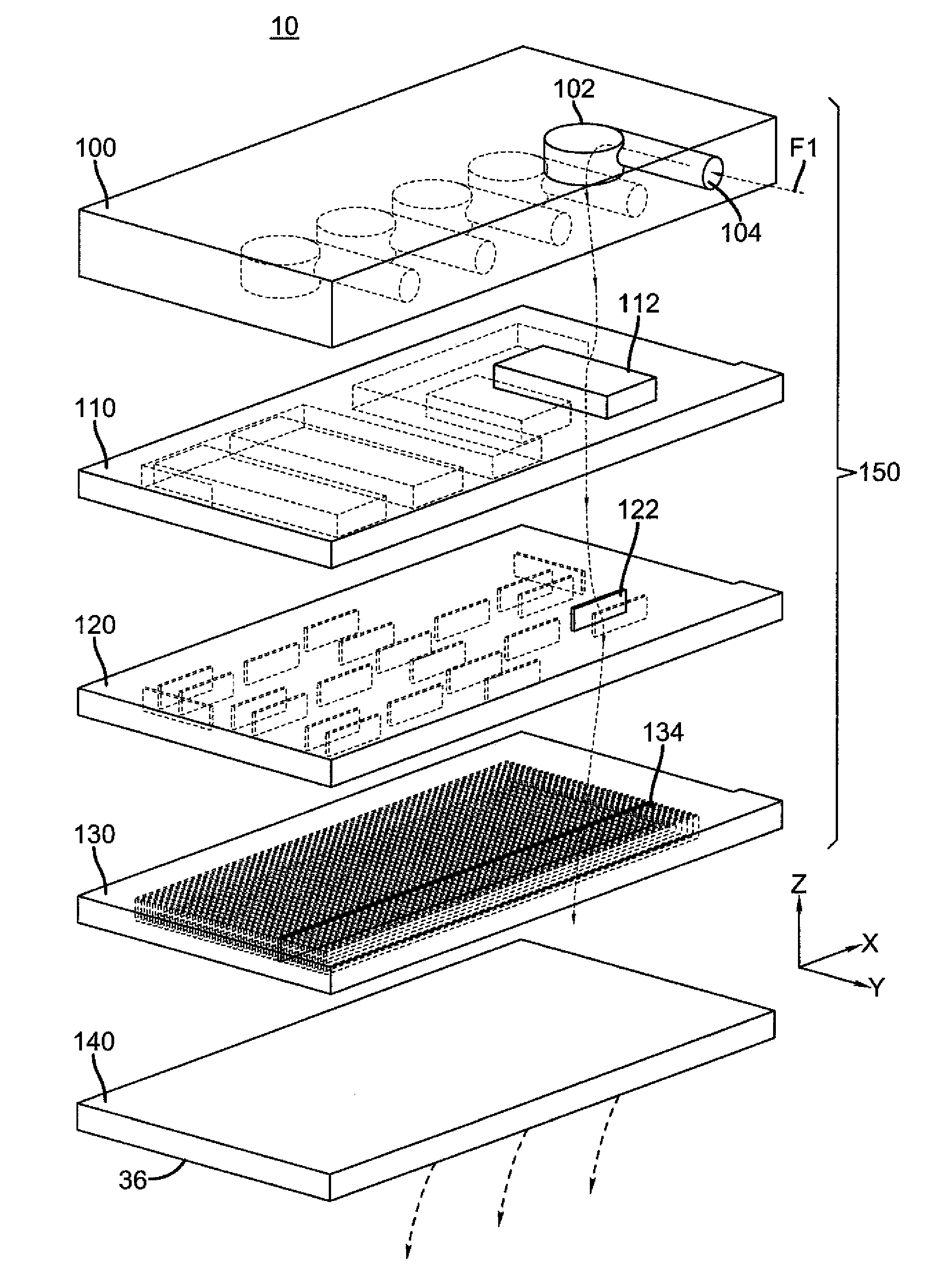
[0082]The present description is directed in particular to diffusing elements forming part of, or cooperating within, an apparatus in accordance with the invention that delivers a fluid material to a substrate. It is to be understood that elements not specifically shown or described may take various forms well known to those skilled in the art.

[0083]More particularly, this invention relates to a means of diffusing a gas flow from a source channel so that it exits uniformly over a longer linear region. While this method may be applied to a broad range of technologies, one important application is in the field of spatially dependent ALD.

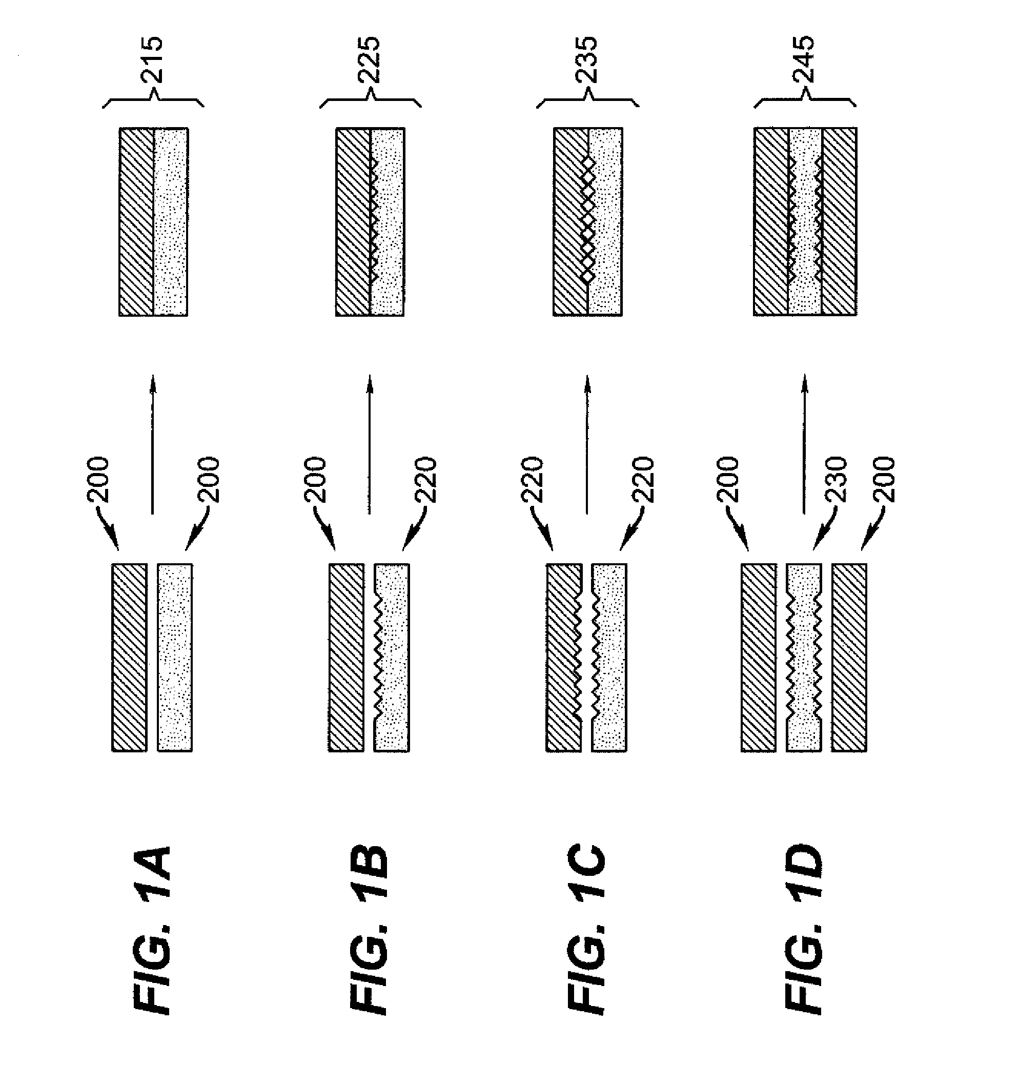
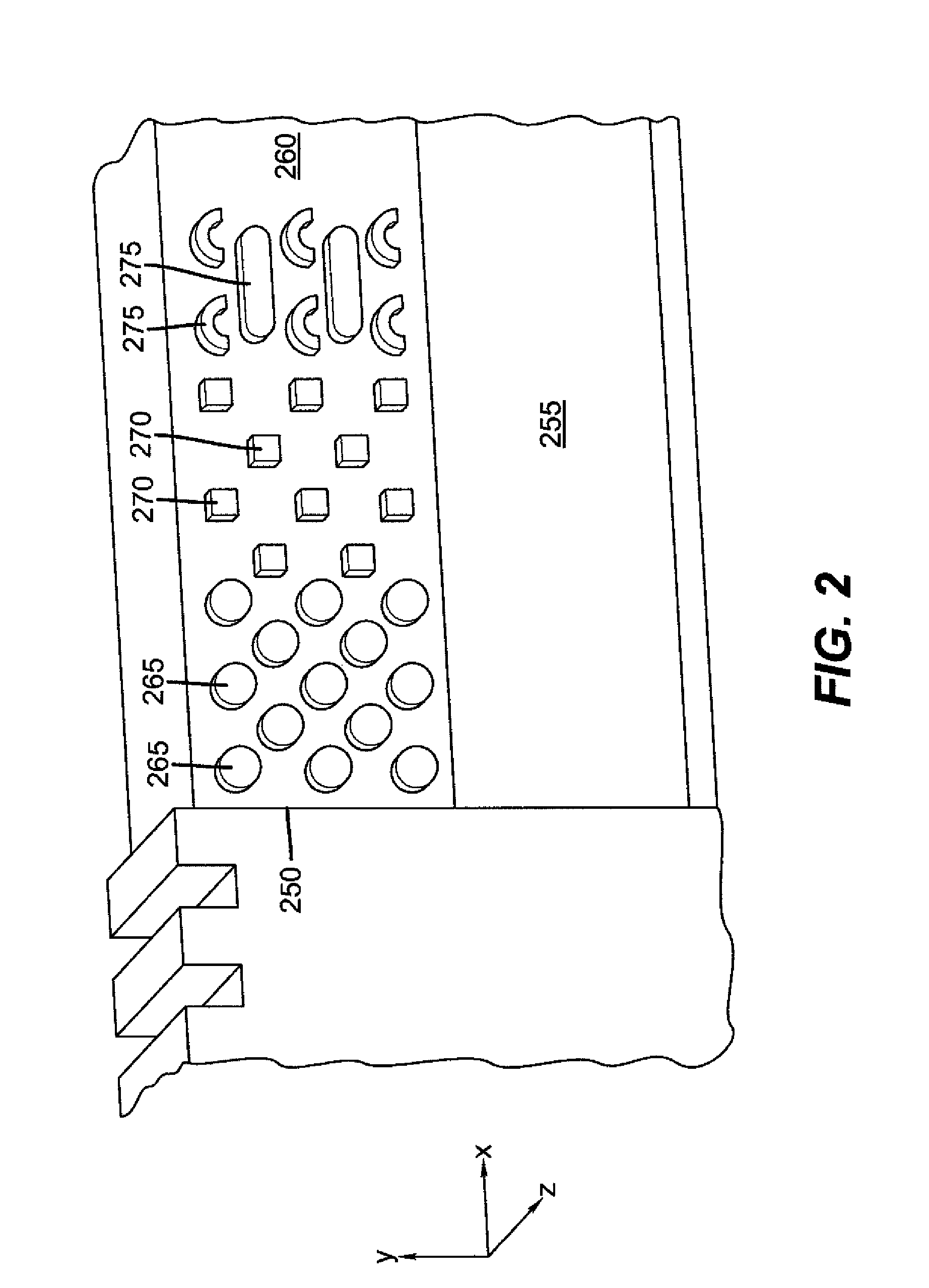
[0084]To suitably diffuse a flow of gas, an element that provides uniform flow backpressure over a linear region must be devised. In order to provide a restriction of flow, a channel needs to be created in which the open cross-section available for flow is very small. To provide suitable backpressures, the open cross-section for flow should have openin...


PUM

PropertyMeasurementUnit
areaaaaaaaaaaa
separation distanceaaaaaaaaaa
thicknessaaaaaaaaaa

Abstract

A delivery device for thin-film material deposition has at least first, second, and third inlet ports for receiving a common supply for a first, a second and a third gaseous material, respectively. Each of the first, second, and third elongated emissive channels allow gaseous fluid communication with one of corresponding first, second, and third inlet ports. The delivery device can be formed from apertured plates, superposed to define a network of interconnecting supply chambers and directing channels for routing each of the gaseous materials from its corresponding inlet port to a corresponding plurality of elongated emissive channels. The delivery device comprises a diffusing channel formed by a relief pattern between facing plates. Also disclosed is a process for thin film deposition. Finally, more generally, a flow diffuser and a corresponding method of diffusing flow is disclosed.

Description

CROSS-REFERENCE TO RELATED APPLICATIONS[0001]The present application is related to U.S. Pat. No. 7,413,982 issued Aug. 19, 2008 by Levy and entitled, “PROCESS FOR ATOMIC LAYER DEPOSITION,” U.S. Pat. No. 7,456,429 issued Nov. 25, 2008 by Levy and entitled “APPARATUS FOR ATOMIC LAYER DEPOSITION,” US Application Publication Number 2008 / 0166880 published Jul. 10, 2008 by Levy and entitled “DELIVERY DEVICE FOR DEPOSITION,” U.S. Pat. No. 7,789,961 issued Sep. 7, 2010 by Nelson et al. and entitled “DELIVERY DEVICE COMPRISING GAS DIFFUSER FOR THIN FILM DEPOSITION,” US Application Publication Number 2009 / 0130858 published May 21, 2009 by Levy and entitled, “DEPOSITION SYSTEM AND METHOD USING A DELIVERY HEAD SEPARATED FROM A SUBSTRATE BY GAS PRESSURE,” US Application Publication Number 2009 / 0078204 published Mar. 26, 2009 by Kerr et al. and entitled, “DEPOSITION SYSTEM FOR THIN FILM FORMATION,” U.S. Pat. No. 7,572,686 issued Aug. 11, 2009 by Levy et al. and entitled “SYSTEM FOR THIN FILM DEPO...

Claims


Application Information

Patent Timeline
Patent Type & Authority Patents(United States)
IPC IPC(8): C23C16/455C23F1/00H01L21/306C23C16/22C23C16/06
CPCC23C16/45551C23C16/45574B05B1/005Y10T29/494Y10T29/49432Y10T29/49826Y10T137/87249Y10T137/0318
Inventor KERR, ROGER S.LEVY, DAVID H.MURRAY, JAMES T.
Owner EASTMAN KODAK CO
Why Eureka
Try Eureka