Method and system for control of a vehicle energy storage device

a technology for energy storage devices and energy storage devices, which is applied in the direction of electric devices, battery/fuel cell control arrangements, hybrid vehicles, etc., can solve the problems of affecting the operating life and performance characteristics of such devices, affecting the operation life and storage capacity of energy storage devices, and frequent cycles of periodic charging and discharging of energy storage devices

Active Publication Date: 2012-07-03
GENERAL ELECTRIC CO
View PDF23 Cites 8 Cited by
  • Summary
  • Abstract
  • Description
  • Claims
  • Application Information

AI Technical Summary

Benefits of technology

[0005]For example, when it is predetermined that a charging opportunity is of a longer duration, the energy storage device may be charged at a lower rate (e.g., with a lower charging current), than when it is predetermined that a charging opportunity is of a shorter duration. Analogously, the discharging rate for an energy storage device may be appropriately adjusted responsive to a known duration of an upcoming discharging opportunity. In this way, it is possible to take advantage of a priori information about the charging / discharging opportunity (e.g., information known, deduced, and / or estimated before the charging / discharging opportunity) to better utilize longer charging / discharging durations through a lower charging / discharging rate. The longer charging / discharging time can further augment battery life and performance due to ancillary benefits such as reduced overall losses. In one example, overall losses can be reduced due to a direct reduction in resistive heat losses (that is energy loss incurred from I2R power loss). In another example, the reduction in overall losses (resistive or otherwise) enables a reduction in the amount of cooling power required, and other thermal management requirements. Such synergistic benefits of the reduction in overall losses can outweigh issues related to time extension of the charging / discharging opportunity. Taken together, such operation thereby provides a more efficient power transfer and reduces degradation of the energy storage device in the vehicle, while still reaching the desired state of charge at the conclusion of the opportunity.

Problems solved by technology

During operation, the energy storage devices experience frequent cycles of periodic charging and discharging.
Further, the operating life and performance characteristics of such devices can be affected by the rate and depth of charging / discharging and / or the current level at which the power transfer occurs.
For example, use of faster and deeper rates of power transfer and higher current (and / or voltage) levels during bulk charging / discharging events can adversely affect the operating life and storage capacity of an energy storage device.
Reduced performance of electrical energy storage devices in turn may affect the fuel efficiency of the vehicle system in which they are used.

Method used


Image

  • Method and system for control of a vehicle energy storage device
  • Method and system for control of a vehicle energy storage device
  • Method and system for control of a vehicle energy storage device

Examples


Embodiment Construction

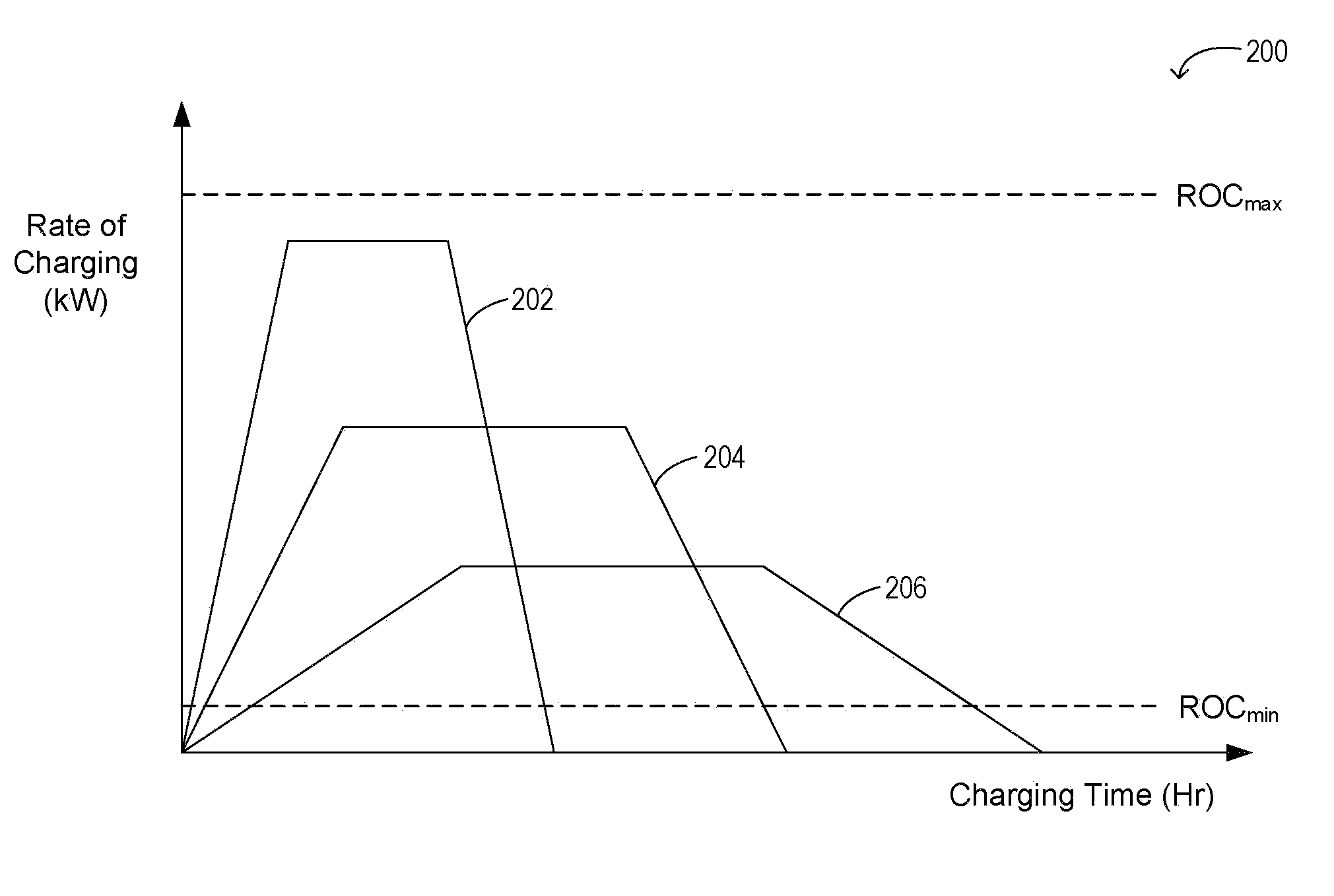
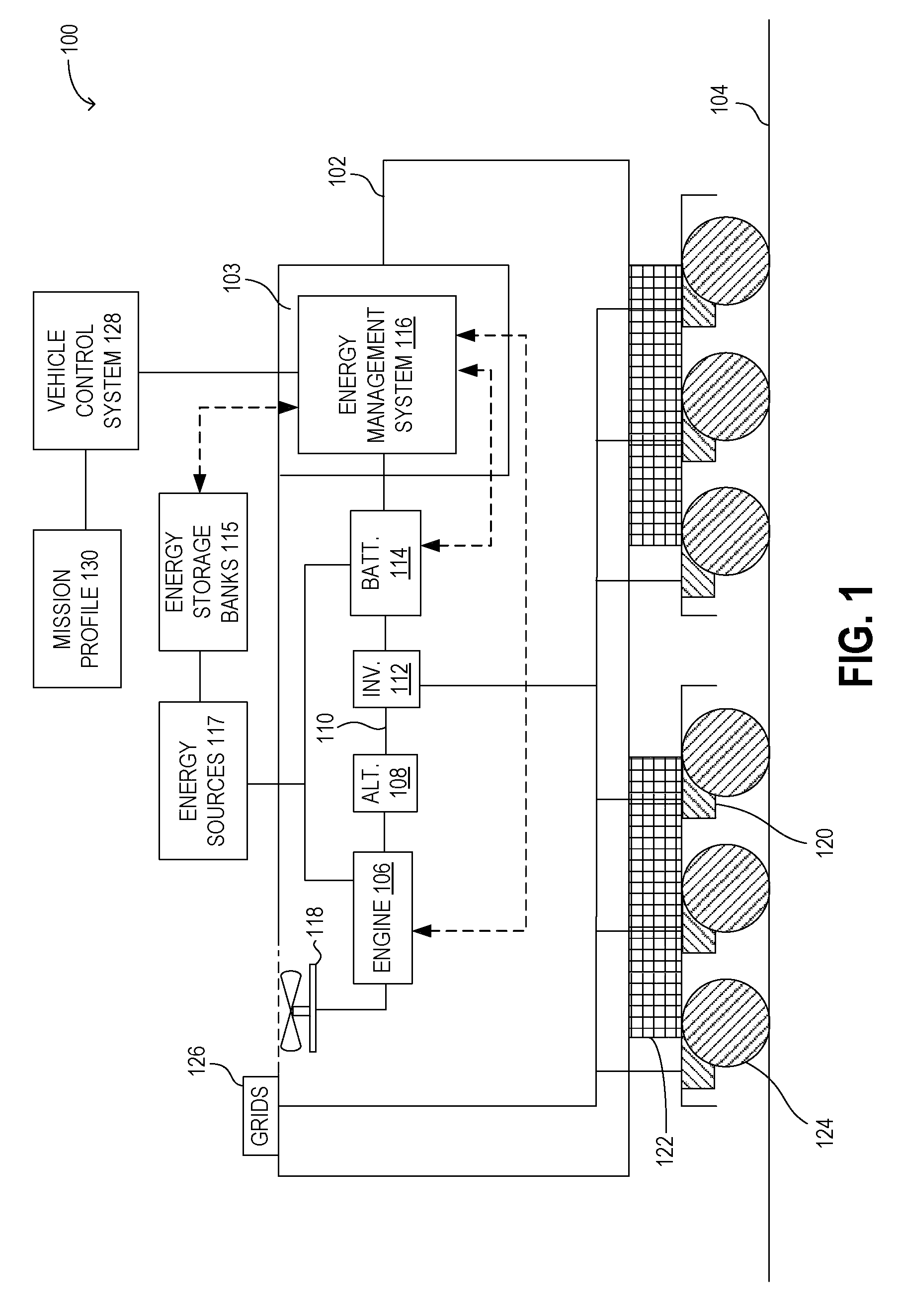
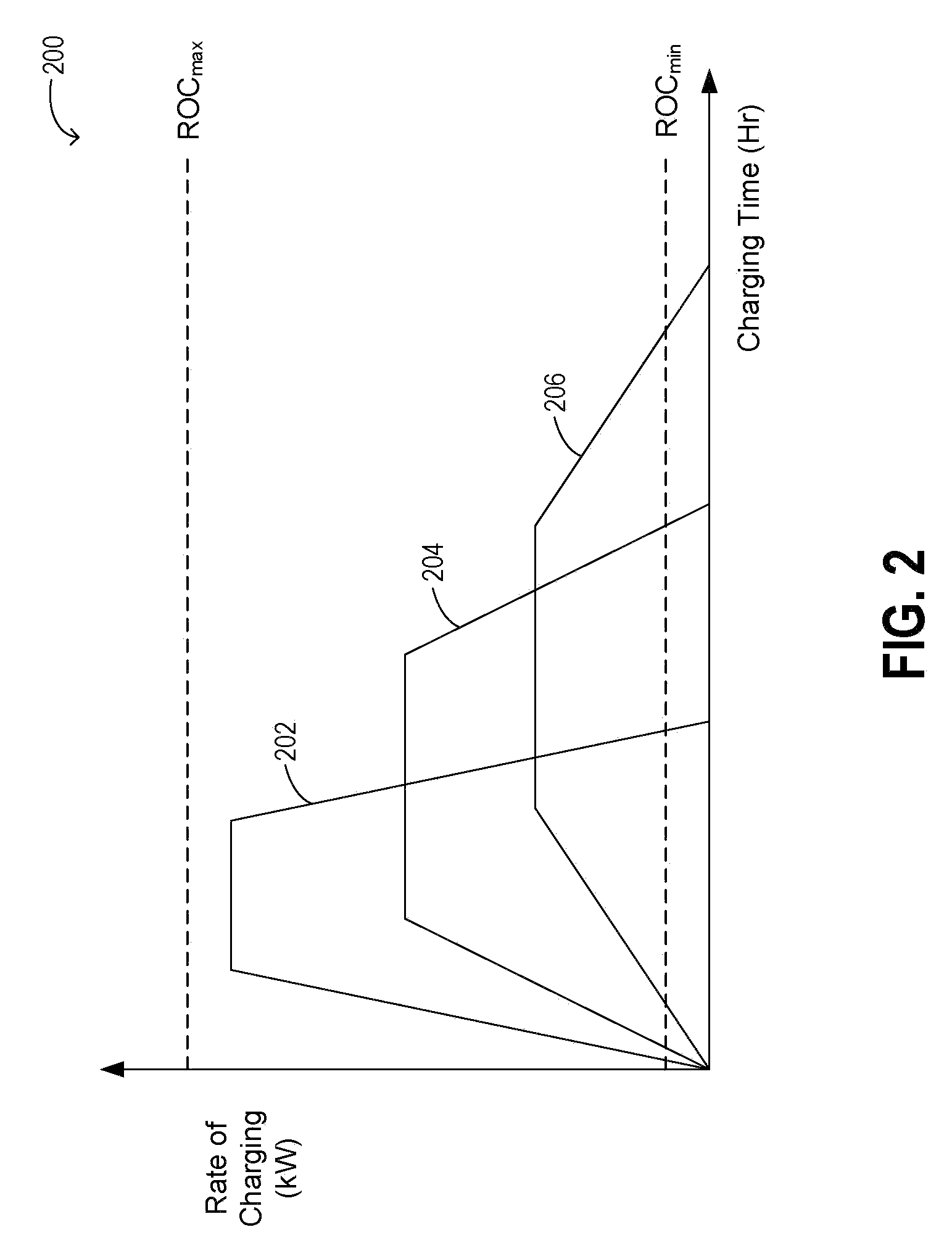
[0011]Vehicles, such as locomotives, operating with rechargeable electrical energy storage devices may be configured with integrated energy management systems that control power transfer rates to and from the energy storage device. The power transfer rate may be controlled based not only on the operating condition of the energy storage device, but also responsive to charging / discharging opportunities available during a mission. One example is illustrated with reference to FIG. 1 wherein an energy management system monitors the operating conditions of a locomotive's on-board electrical energy storage device, and based on the duration of the power transfer opportunity, adjusts the charging / discharging profile so as to enable an efficient power transfer. In doing so, the operating life of the energy storage device may be extended while reducing the failure rate. In the event of multiple energy storage banks, the power transfer profile may be customized responsive to the age, capacity, ...


PUM


Abstract

Systems and methods are described for controlling a power transfer rate in to and / or out of an energy storage device on-board a vehicle, such as a locomotive, during a power transfer opportunity. In one example, the method includes adjusting the power transfer rate based on a predetermination of a duration of the power transfer opportunity to match a duration of power transfer to the duration of the opportunity and achieve a specified state of charge.

Description

FIELD[0001]The subject matter disclosed herein relates to a method and system for improving the power transfer profile of a vehicle energy storage device to thereby improve the operating life of the device.BACKGROUND[0002]Electric and hybrid electric vehicles, such as locomotives, operate with on-board rechargeable electrical energy storage devices. The energy storage devices may include one or more types of batteries, super-capacitors, and flywheel systems.[0003]During operation, the energy storage devices experience frequent cycles of periodic charging and discharging. Further, the operating life and performance characteristics of such devices can be affected by the rate and depth of charging / discharging and / or the current level at which the power transfer occurs. Related changes in the device's state of charge and temperature can also affect its life and performance characteristics. For example, use of faster and deeper rates of power transfer and higher current (and / or voltage) ...

Claims


Application Information

Patent Timeline
Patent Type & Authority Patents(United States)
IPC IPC(8): H02J7/00B60L50/15
CPCB60L3/0046B60L7/06B60L11/123B60L11/1861B60L11/1864B60L11/1874B60L2200/26Y02T10/6217Y02T10/7005Y02T10/7044Y02T10/7061Y02T10/7077B60L50/61B60L58/14B60L58/15B60L58/18B60L58/21B60L58/26Y02T10/62Y02T10/70Y02T10/7072
Inventor KUMAR, AJITH KUTTANNAIR
Owner GENERAL ELECTRIC CO
Why Eureka
Try Eureka