Diaphragm pumps and transporting drag reducers

a technology of diaphragm pumps and reducers, which is applied in the direction of positive displacement liquid engines, engine diaphragms, machines/engines, etc., can solve the problems of pipelines that limit the amount of pressure that can be employed, the problem of fluid pressure dropping is typically occurring, and the problem of pressure drop is the most acute problem. to achieve the effect of reducing the pressure drop

Active Publication Date: 2012-07-10
LIQUIDPOWER SPECIALTY PROD INC
View PDF13 Cites 6 Cited by
  • Summary
  • Abstract
  • Description
  • Claims
  • Application Information

AI Technical Summary

Benefits of technology

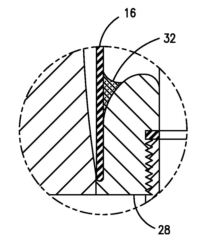
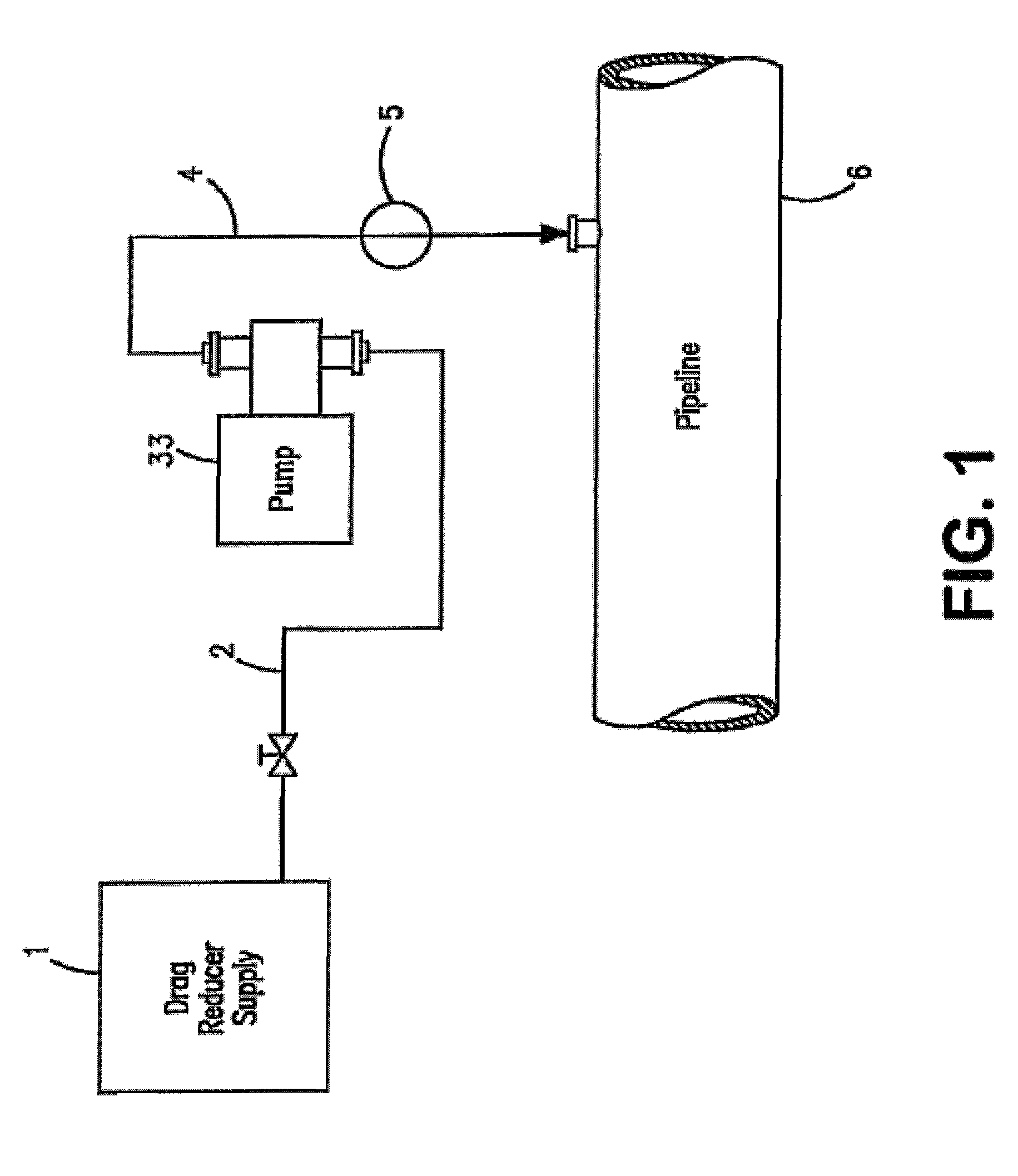
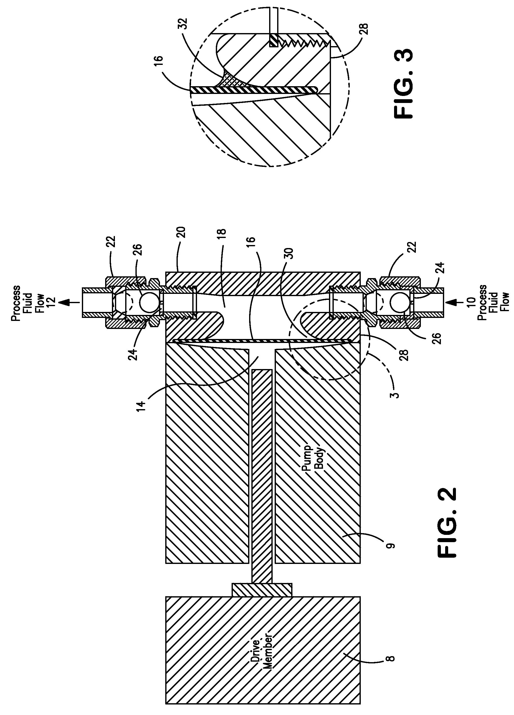
[0010]In accordance with still another embodiment of this invention, a method is provided for reducing the pressure drop associated with flowing a hydrocarbon-containing fluid through a pipeline, said process comprising (a) preparing a latex drag reducer via emulsion polymerization; and (b) pumping at least a portion of said latex drag reducer into said hydrocarbon-containing fluid via a diaphragm pump, said diaphragm pump comprising 1) a diaphragm having a pump side and an actuation side; and 2) a pump head circumferentially coupled to said pump side of said diaphragm, thereby defining a pumping chamber, wherein said pumping comprises causing said diaphragm to oscillate between a suction stroke position and a discharge stroke position thereby causing at least a portion of said latex drag reducer to flow through said pumping chamber, wherein said latex drag reducer is prevented from contacting at least 50 percent of the circumferential interface between said pump side of said diaphragm and said pump head by at least one barrier material.

Problems solved by technology

When fluids are transported by a pipeline, a drop in fluid pressure typically occurs due to friction between the wall of the pipeline and the fluid.
However, design limitations on pipelines limit the amount of pressure that can be employed.
The problems associated with pressure drop are most acute when fluids are transported over long distances.
Such pressure drops can result in inefficiencies that increase equipment and operation costs.
The role of these additives is to suppress the growth of turbulent eddies, which results in higher flow rate at a constant pumping pressure.
As improved drag reducers are developed, the pumps available to pump the drag reducers into pipelines cannot always effectively pump drag reducers and maintain pump pressure.
The pumps can become plugged with drag reducer or other components and valuable time is spent to open, clean and maintain the pumps.

Method used


Image

  • Diaphragm pumps and transporting drag reducers
  • Diaphragm pumps and transporting drag reducers
  • Diaphragm pumps and transporting drag reducers

Examples


example 1

No Barrier Material Test

[0036]This Example demonstrates pumping Latex A through an HPD pump with no barrier material. The results, shown in FIG. 4, show numerous large and sudden decreases in pumping rate which are indication that the pump discharge check valve is being plugged or partially blocked. The pump test was stopped after about four days to examine the solids. These “blips” in rate were as short as a couple of minutes to as long as a few hours. Upon dismantling the pump head, a visual inspection of the pump head showed a significant amount of polymer film on the diaphragm. This film appeared to be breaking off the pump head and moving through the discharge check valve.

example 2

Polyurethane Barrier Material Test

[0037]This Example demonstrates pumping Latex A through an HPD pump with PL® Polyurethane Door, Window and Siding Sealant, marketed by Henkel Corporation as the barrier material. The results, shown in FIG. 5, show improved pumping stability. The pump test was stopped after about four days to examine the solids. A visual inspection showed polymer film had formed on the barrier material in locations where the barrier material came loose from the pump head, but there was minimal amount of solids present where the barrier material was still in contact with the pump head.

example 3

Glued-On Polyurethane Barrier Material Test

[0038]A test similar to Example 2 was repeated in which the PL® Polyurethane Door, Window and Siding Sealant, marketed by Henkel Corporation, was allowed to cure in place in the pump head and then was removed and glued, with Elmer's E617® super glue gel, to the metal pump head to be able to hold it in place better. The results, shown in FIG. 6, show a nice smooth flow rate plot for 14 days. The pump test was stopped at that time to examine the solids. A visual inspection showed that polymer solids developed in the pump head but they were only present where the barrier material came loose from the pump head.


PUM


Abstract

An apparatus for a diaphragm pump and a method for transporting at least a portion of a latex and / or a latex drag reducer through a diaphragm pump are disclosed. A method for reducing the pressure drop associated with flowing a hydrocarbon-containing fluid through a pipeline also is disclosed.

Description

BACKGROUND OF THE INVENTION[0001]1. Field of the Invention[0002]The invention relates to an improved pump and process for pumping latexes or latex drag reducing agents, also referred to as drag reducing additives or flow improvers. More particularly, the invention relates to diaphragm pumps, a method to transport a latex drag reducer, and a method to reduce the pressure drop associated with flowing a hydrocarbon-containing fluid through a pipeline.[0003]2. Description of the Prior Art[0004]When fluids are transported by a pipeline, a drop in fluid pressure typically occurs due to friction between the wall of the pipeline and the fluid. Due to this pressure drop, for a given pipeline, fluid must be transported with sufficient pressure to achieve a desired throughput. When higher flow rates are desired through the pipeline, more pressure must be applied due to the fact that as flow rates are increased the difference in pressure caused by the pressure drop also increases. However, desi...

Claims


Application Information

Patent Timeline
Patent Type & Authority Patents(United States)
IPC IPC(8): F04B45/04F01B19/02F16J3/02
CPCF04B15/02F04B15/04F04B43/067F17D1/17Y10T137/0391
Inventor BURDEN, TIMOTHY L.NGUYEN, DUNG H.THOMAS, RICHARD D.
Owner LIQUIDPOWER SPECIALTY PROD INC
Why Eureka
Try Eureka