Light emitting device, package, light emitting device manufacturing method, package manufacturing method and package manufacturing die

a technology of light emitting devices and manufacturing methods, applied in the direction of solid-state devices, semiconductor/solid-state device details, coatings, etc., can solve the problems of poor heat resistance and adhesiveness of thermoplastic resin to lead frame, low fluidity of resin, and disturbed bending work, etc., to achieve the effect of large stress

Active Publication Date: 2012-07-10
NICHIA CORP
View PDF18 Cites 30 Cited by
  • Summary
  • Abstract
  • Description
  • Claims
  • Application Information

AI Technical Summary

Benefits of technology

[0042]According to the light emitting device and package of the present invention, since the light emitting device and package has the first resin mold body provided with the strong weld line, the light emitting device and package can be prevented from generating cracks. In addition, according to the package manufacturing die described above, since the first resin mold body provided with the strong weld line can be formed, the package can be prevented from generating cracks. According to the manufacturing method of the light emitting device and manufacturing method of the package, since the first resin mold body provided with the strong weld line can be formed, the light emitting device and package can be prevented from generating cracks. Especially, if a resin having a large thermal expansion coefficient such as silicone resin or modified silicone resin is used for the second resin mold body, the second resin mold body largely expands and contracts on heating and cooling. Due to the expansion and contraction of the second resin mold body at the time, an extremely large stress is generated in the first resin mold body. However, since a sufficient strength is secured in the weld portion, the light emitting device and package can be prevented from generating cracks.

Problems solved by technology

However, there have been the following problems in the molding method 1.
In addition, if the gate remain 106 is formed at the bottom center of the resin mold body 104, this causes a problem (2) that when the lead frames 102, 103 are bended, the bending work is disturbed since a bending machine is caught in the cutting remain of the gate remain 106.
Further, in the molding method 1, since a thermoplastic resin is used, a fluidity of the resin is low, and as a result, the molding method 1 is inappropriate for molding the resin mold body 104 having a complex shape.
In addition, there has been a problem (3) that a thermoplastic resin is poor in heat resistance and adhesiveness to the lead frame.

Method used


Image

  • Light emitting device, package, light emitting device manufacturing method, package manufacturing method and package manufacturing die
  • Light emitting device, package, light emitting device manufacturing method, package manufacturing method and package manufacturing die
  • Light emitting device, package, light emitting device manufacturing method, package manufacturing method and package manufacturing die

Examples


first embodiment

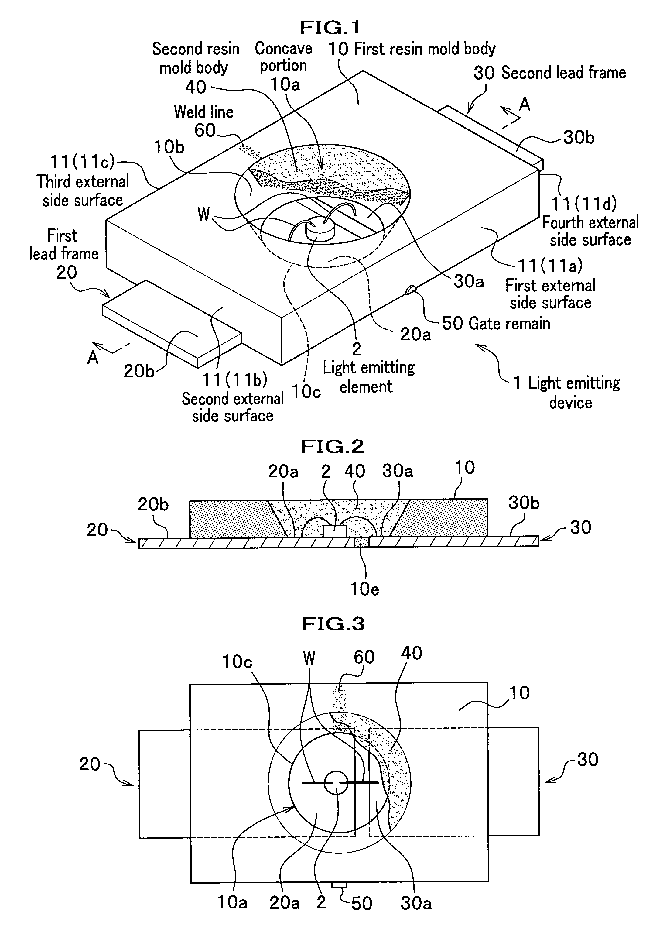
[0077]FIG. 1 is a perspective view showing a light emitting device according to a first embodiment of the present invention. FIG. 2 is an illustration showing the light emitting device according to the first embodiment of the present invention, and which is a cross sectional view taken along A-A line of FIG. 1. FIG. 3 is a plan view showing the light emitting device according to the first embodiment of the present invention.

[0078]The light emitting device 1 according to the first embodiment includes a light emitting element 2, a first resin mold body 10 on which the light emitting element 2 is placed, a first lead frame 20 and a second lead frame 30 which are arranged underneath the first resin mold body 10 and electrically connected to the light emitting element 2, and a second resin mold body 40 to be filled in a concave portion 10a of the first resin mold body 10. In addition, a gate remain 50 is formed on a side surface of the first resin mold body 10 and a weld line 60 is forme...

first modified example

[0156]FIG. 7 is a plan view showing a first modified example of a package according the present invention.

[0157]As shown in FIG. 7, a package 90 of the first modified example is different from the first embodiment in that six lead frames 21 are arranged and that a shape of a concave portion 12 is an ellipsoidal shape in plan view. That is, the package 90 includes the first resin mold body 10 which has a rectangular shape in plan view and has the first external side surface 11a, the second external side surface 11b, the third external side surface 11c, and fourth external side surface 11d, a first lead frame 21a disposed at the center of the first external side surface 11a, a second lead frame 21b and third lead frame 21c disposed on the second external side surface 11b with a predetermined interval, a fourth lead frame 21d disposed at the center of the third side surface 11c, and a fifth lead frame 21e and sixth lead frame 21f disposed on the fourth external side surface 11d with a ...

second modified example

[0161]FIG. 8 is a plan view showing a second modified example of a package according to the present invention.

[0162]As shown in FIG. 8, a package 92 of the second modified example is different from that of the first modified example in that a weld line 62 is formed diagonally in a first resin mold body 13 and that the first resin mold body 13 has a square shape in plan view. That is, the package 92 includes the first resin mold body 13, which has a square shape in plan view, having a first external side surface 14a, a second external side surface 14b, a third external side surface 14c, and a fourth external side surface 14d, a first lead frame 22a and second lead frame 22b disposed on the second external side surface 14b with a predetermined interval, and a third lead frame 22c and fourth lead frame 22d disposed on the fourth external side surface 14d with a predetermined interval. In addition, the first resin mold body 13 is provided with a concave portion 10a having a circular sha...


PUM

PropertyMeasurementUnit
opening angleaaaaaaaaaa

Abstract

Provided is a light emitting device wherein a resin molded body having a circular or an oval recessed section at the center suppresses generation of cracks. A light emitting device (1) is provided with a light emitting element (2); a first resin molded body (10) having a plurality of outer surfaces (11), and a recessed section (10a) at the center; a first lead (20) and a second lead (30) electrically connected to the light emitting element (2); and a second resin molded body (40) applied in the recessed section (10a). The light emitting element (2) is place on the first lead (20), and the surface of the second resin molded resin (40) is permitted to be a light emitting surface. A gate notch (50) obtained by cutting a gate formed on the outer surface (11) of the first resin molded body (10) is formed on an extended line of a normal line on one point on a circular cross-section of the recessed section (10a) in the normal nine direction.

Description

TECHNICAL FIELD[0001]The present invention relates to a light emitting device to be used for, for example, lighting apparatuses, displays, a backlight of cellular phone, an auxiliary light source for animation illumination, and other general consumer light sources, a package suitable for the light emitting device, a manufacturing method of the light emitting device, a manufacturing method of the package, and a package manufacturing die.BACKGROUND ART[0002]Generally, it is well known that a light emitting device using a light emitting element is compact and excellent in power efficiency and emits bright colors. The light emitting element used for the light emitting device is a semiconductor device. Therefore, the light emitting element is excellent in an initial drive performance in addition to almost free from blowout, and resistant to vibrations and repetitions of ON / OFF switching. Since the light emitting element has excellent characteristics as described above, a light emitting d...

Claims


Application Information

Patent Timeline
Patent Type & Authority Patents(United States)
IPC IPC(8): H01L33/00H01L33/52
CPCB29C45/0025B29C45/1671B29C45/0046B29C45/14655B29C2045/0027H01L33/52H01L2224/48091H01L2924/3025H01L2224/48247H01L2924/00014H01L2924/00
Inventor HAYASHI, MASAKI
Owner NICHIA CORP
Why Eureka
Try Eureka