Recycling method for electronics scrap in order to obtain reusable materials while avoiding the release of harmful substances

a technology of electronic scrap and recycling method, which is applied in the field of electronic waste dressing, can solve the problems of not even minimizing the escape of such stuff, comminuting such waste in a non-predictable way, and destroying the original material, so as to avoid any negative influence on the environment

Active Publication Date: 2012-07-17
KOSLOW ALEXANDER
View PDF9 Cites 2 Cited by
  • Summary
  • Abstract
  • Description
  • Claims
  • Application Information

AI Technical Summary

Benefits of technology

[0013]It is essential for this invention that, besides the usage of known procedural steps, destruction of housings is executed in such a careful manner that a violation of noxious particles containing material components is avoided.
[0018]Separation of bulky and big construction elements (made from aluminium, copper, precious metal and similar materials or plastics) in order to protect comminution machinery and to extend its tool life.
[0026]This invention comprises a process, which contains a pre-dressing system which consists of several individual steps that follow needless one-another and that does not exclude feedback steps so that utmost efficiency and purity of different sorts of recovered stuff is warranted. Linked to that is minimizing of costs for the construction of the installations for carrying out such process.
[0027]It is essential for the whole process line of this first mechanical dressing for separation purpose of electronic waste by using a smasher. Smashers per se are already known, however, their functional importance for dressing electronic waste has not yet earlier been detected. Such a smasher may be designed as a rotating drum, which comprises at least one smasher room at which carriers attached to rotating walls were distributed all over the interior wall side. The drum that is preferably centrally fixed in a rotational way in bearings on each closed front side of the drum. The bearings are pivoted to bearing stocks that are fixed to foundations. The drum is equipped with an adjustable drive. Varying the revolution of the drum may influence the intensity of destruction of the conglomerate of waste. There are also known construction of smashers with a non movable drum-housing but this type is equipped with carries fixed to a rotating support unit that is open to the interior surrounding wall and which rotating speed is preferably also adjustable. This type of smasher may have located opposite to the culmination point of the drum housing damping material may be filled into a groove that damps the down falling of the material thus reducing destruction energy and enabling adaptation to the needs of individual type of material in order to avoid escaping of noxious particles. For this purpose it is also possible to have drum housing and support unit for carriers rotating in the same or opposite direction at equal or different speed. It is self evident that the interior of the drum has an inlet opening for the material to be treated and an outlet opening for the material already finished.

Problems solved by technology

A disadvantage for such procedures and related machinery is that for comminution of electronic waste hammer-mills are used, which comminute such waste in a non-predictable way.
However, all these measures comprise one essential deficit, which is to be seen in, when starting the process a mechanical comminution takes place and in consequence a destruction of the original material construction happens earlier to the removal of components containing noxious particles.
Hence, noxious stuff may escape into the environment or the escape of such stuff is not even minimized.
Such procedures do not meet any more legal regulations and hence, cannot anymore be accepted.
Therefore, known sites can only handle electronic waste that was earlier cleared from noxious material.
Manual pre-sorting, without a comminution of housings, is not only inefficient and time consuming, but also demands for a high financial contribution.

Method used


Image

  • Recycling method for electronics scrap in order to obtain reusable materials while avoiding the release of harmful substances
  • Recycling method for electronics scrap in order to obtain reusable materials while avoiding the release of harmful substances

Examples


Embodiment Construction

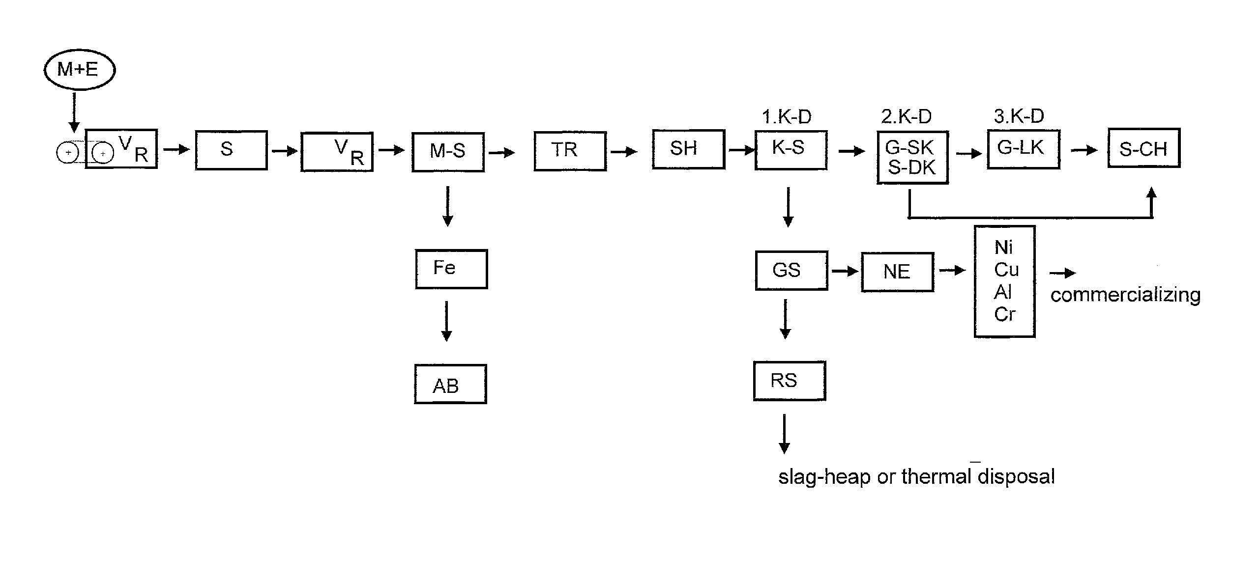
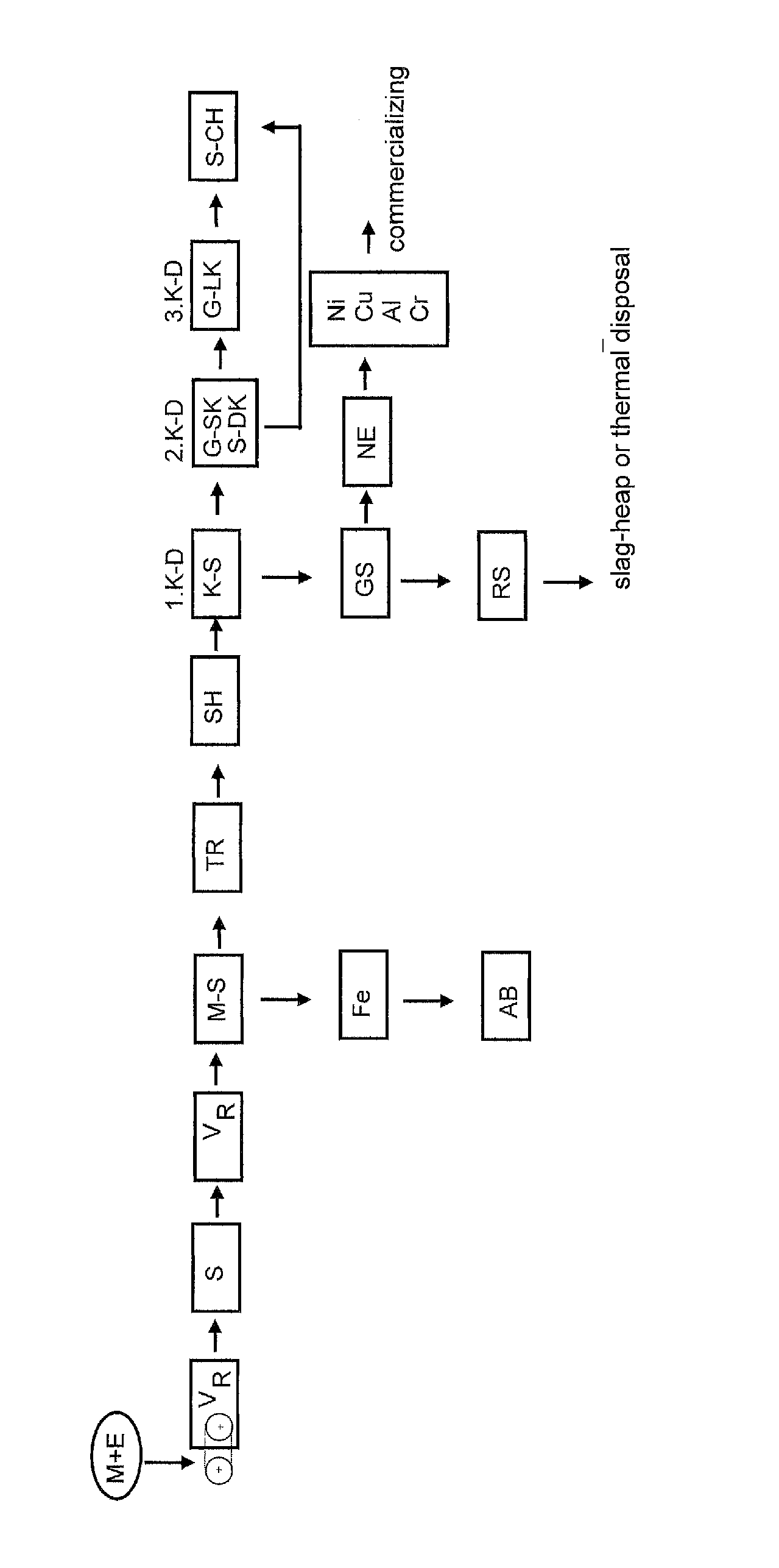
[0039]Electronic waste is taken to a closed room (R) by a conveyer-belt (B) where a manual or mechanical pre-selection takes place, for sorting out e.g. cables, mercury switches etc. that contain toxic particles or tend to form lumps. After having passed this pre-sorting (V) stage electronic waste is comminuted in a so-called smasher (S). A smasher is a cylindrical drum (as already described) with a large diameter that takes the material filled in to the highest spot and then makes it fall down for having fragile construction elements bursting by impact on the lower part of that drum. However, condensers and similar parts do not burst, since the impact can be controlled. By such a way of destruction noxious particles originating from those construction elements cannot escape. Though it differs from working on such construction elements by all other type of destruction machinery as shredders (SH), or hammer-mills and similar machinery, which destroy such construction elements by cutt...


PUM

PropertyMeasurementUnit
ferro-magneticaaaaaaaaaa
volumeaaaaaaaaaa
densityaaaaaaaaaa

Abstract

A process for industrial disposal for electro-waste. The process contains steps for separating material that are contained in such waste, for re-introducing material into a re-using process in order to save resources and to meet ecologic and economic interests.

Description

CROSS-REFERENCE TO RELATED APPLICATIONS[0001]The present application is a continuation of pending International patent application PCT / DE2009 / 000352 filed on Mar. 14, 2009 which designates the United States and the content of which is incorporated herein by reference.FIELD OF THE INVENTION[0002]The invention is directed to dressing of electronic waste for recovering re-usable material. Individual processing steps are necessary in order to avoid escape of toxic stuff into atmosphere contained in such waste, since such waste comprises a plurality of different materials. There are still closed electronic components that contain toxic material that is released by physical or thermal destruction, e.g. electronic tubes, capacitors etc.BACKGROUND OF THE INVENTION[0003]There are already known processes by which electronic waste is treated at deep temperature for the purpose to brittle plastic materials in order to facilitate their later comminution. In a follow-up process iron and non iron ...

Claims


Application Information

Patent Timeline
Patent Type & Authority Patents(United States)
IPC IPC(8): B02C19/00
CPCB29B17/02B29B17/04B03B9/061B29B2017/0244B29B2017/0268B29B2017/0272B29K2105/065Y02W30/52Y02W30/62
Inventor KOSLOW, ALEXANDER
Owner KOSLOW ALEXANDER
Why Eureka
Try Eureka