Power supply

a power supply and power supply technology, applied in the direction of electric variable regulation, process and machine control, instruments, etc., can solve the problems of affecting the operation of the power supply, requiring substantial size and requisite weight of the core, and bulky transformers that are difficult to package, so as to reduce the startup stress of electronic devices, easy to detect and regulate, and quick adjustment and compensation

Active Publication Date: 2012-07-17
PHILIPS IP VENTURES BV
View PDF29 Cites 74 Cited by
  • Summary
  • Abstract
  • Description
  • Claims
  • Application Information

AI Technical Summary

Benefits of technology

[0013]In one embodiment, the primary-side control circuitry may adjust the duty cycle of the secondary-side switching circuitry through the isolation circuitry. In this embodiment, the secondary-side circuitry may include measurement circuitry that measures the voltage and / or current of the secondary-side switching circuitry output and sends a corresponding signal to the control circuitry in the primary-side circuitry. This signal may be sent through the isolation circuitry. The primary-side control circuitry may control the duty cycle of the secondary-side switching circuitry as a function of the measured voltage and / or current. The control circuitry may also monitor the measured current received from the measurement circuitry to look for the presence of over-current situations. The control circuitry may reset, disable or otherwise respond to the presence of an over-current situation.
[0017]The air core transformer does not store energy in the same manner as a cored-transformer, so in the event of a short circuit, the primary side of the inductive coil may react much faster than an iron core transformer and the energy remaining in the secondary side of the inductive coil of the air core transformer is quickly dissipated. This fault detection ability and quick recovery is not present in traditional iron core transformers. As a result, if a short circuit occurs, the traditional transformer may continue to provide power until a line circuit breaker trips, or the cause of the short circuit is removed. This situation is undesirable and is potentially hazardous as well. In many applications, traditional transformers are used in applications where the likelihood of a short circuit is greater. For example, in outdoor lighting applications, wired lamps are powered by a transformer. The power supply wire is buried within landscaping, but is exposed to water and the elements. Due to the lamps' location in landscaping areas, the power supply wire is more likely to be in jeopardy from sharp tools are used to tend to the neighboring flora. It is conceivable that a sharp tool could cut or damage the power supply wire, resulting in a short circuit situation. Due to the rapid response of the air-core transformer as disclosed herein, if such an event were to occur, the voltage in the line would be halted relatively quickly.
[0019]Another advantage of the resonant air core transformer is its ability to quickly adjust and compensate for fluctuations in mains voltage. In the event of a power spike or sag, the power supply easily detects and regulates the secondary side voltage to prevent under- or over-voltage conditions. The logic or circuitry of the power supply senses changes in the mains voltage and adjusts appropriately in an effort to preserve any attached devices drawing a load. Thus, the resonant air core transformer helps to protect devices from damage due to mains power abnormalities.
[0020]Another feature of the power supply is its ability to be soft-started using control circuitry to reduce startup stress on electronic devices. Soft-starting is the ability to ramp up or slowly increase power supplied to a device(s) so as to avoid damaging it. Many sensitive modern devices require or benefit from a soft-start and can be damaged if a soft-start is not used. Additionally, soft-starting may extend the life of many devices by placing less stress on energized components.

Problems solved by technology

One disadvantage of transformers using an iron core is that to achieve the necessary performance, the core had to be of a substantial size and requisite weight.
This results in transformers that are bulky and difficult to package.
In many cases these bulky transformers consume precious space, such as those transformers built directly into the mains plug, such that the transformer blocks other outlets, as can be the case in power strips or wall outlets.
If the transformer is to be wall mounted, certain applications may not be suitable due to the excess weight placed upon wall mounts.
Also, the cost of the iron in traditional transformers is also an undesirable factor.
In addition to the direct material cost of iron or other ferrous metals, the traditional transformer must be made larger to accommodate the large coil, necessitating the use of additional other materials, such as plastic, increasing cost.
Copper wire or other conductive material is used abundantly in forming the primary and secondary coils, further adding to the cost of traditional transformers.
Because energy is stored in the iron core, in the event of a short circuit, it can take considerable time for the energy to dissipate from the system, which could cause damage.
As a result, if dimming is required, a power supply with a transformer is not a desirable selection as a power supply.
Unfortunately, a power supply with a traditional transformer is not usable in this application.
Voltage drop over a distance has plagued power supplies with traditional transformers.
A power supply with a traditional transformer may have difficulty adequately powering the lights, and the lights at the very end may be dim or fail to light at all.
This situation is undesirable and places unnecessary limits on landscape lighting, or other applications.
Yet another disadvantage of an iron core transformer is the inability to compensate for fluctuations in mains voltage.
If there is a power spike or sag, the iron core transformer is not equipped to protect the devices it is powering, which could result in permanent damage.
Since many modern electronic devices are sensitive to such power fluctuations, use of a traditional transformer with these devices could result in damage or destruction of these devices.

Method used


Image

  • Power supply
  • Power supply
  • Power supply

Examples


Embodiment Construction

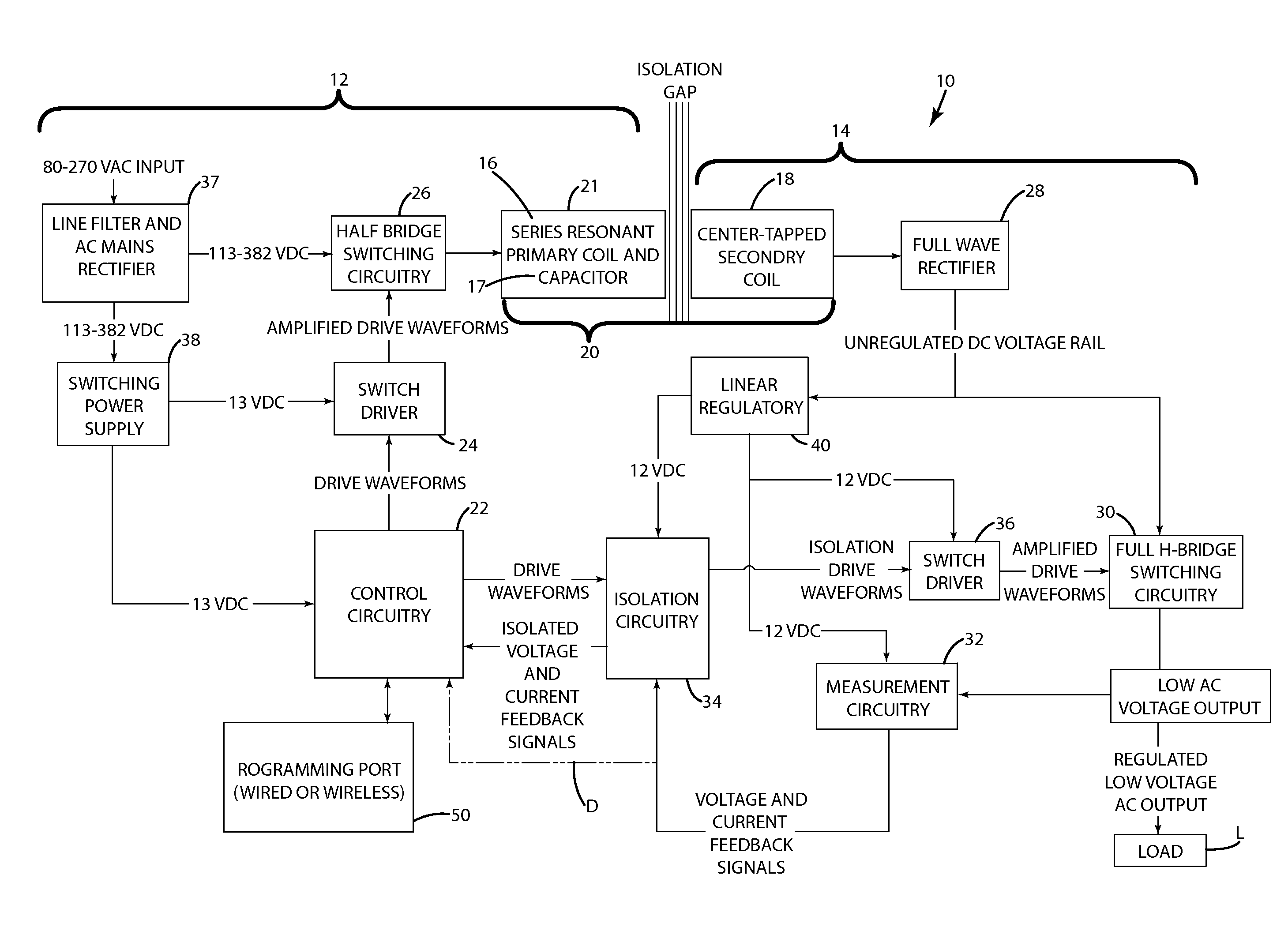
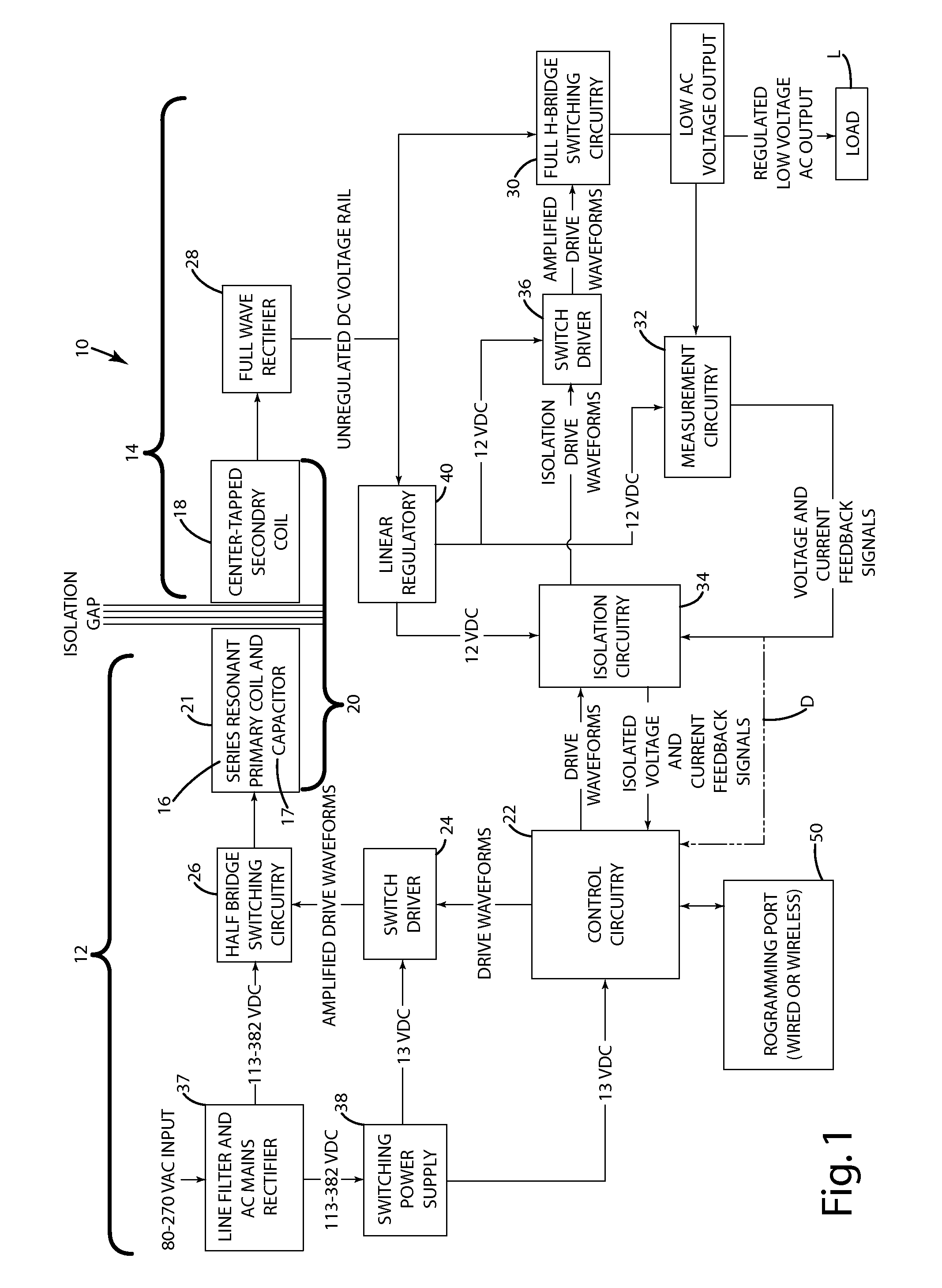
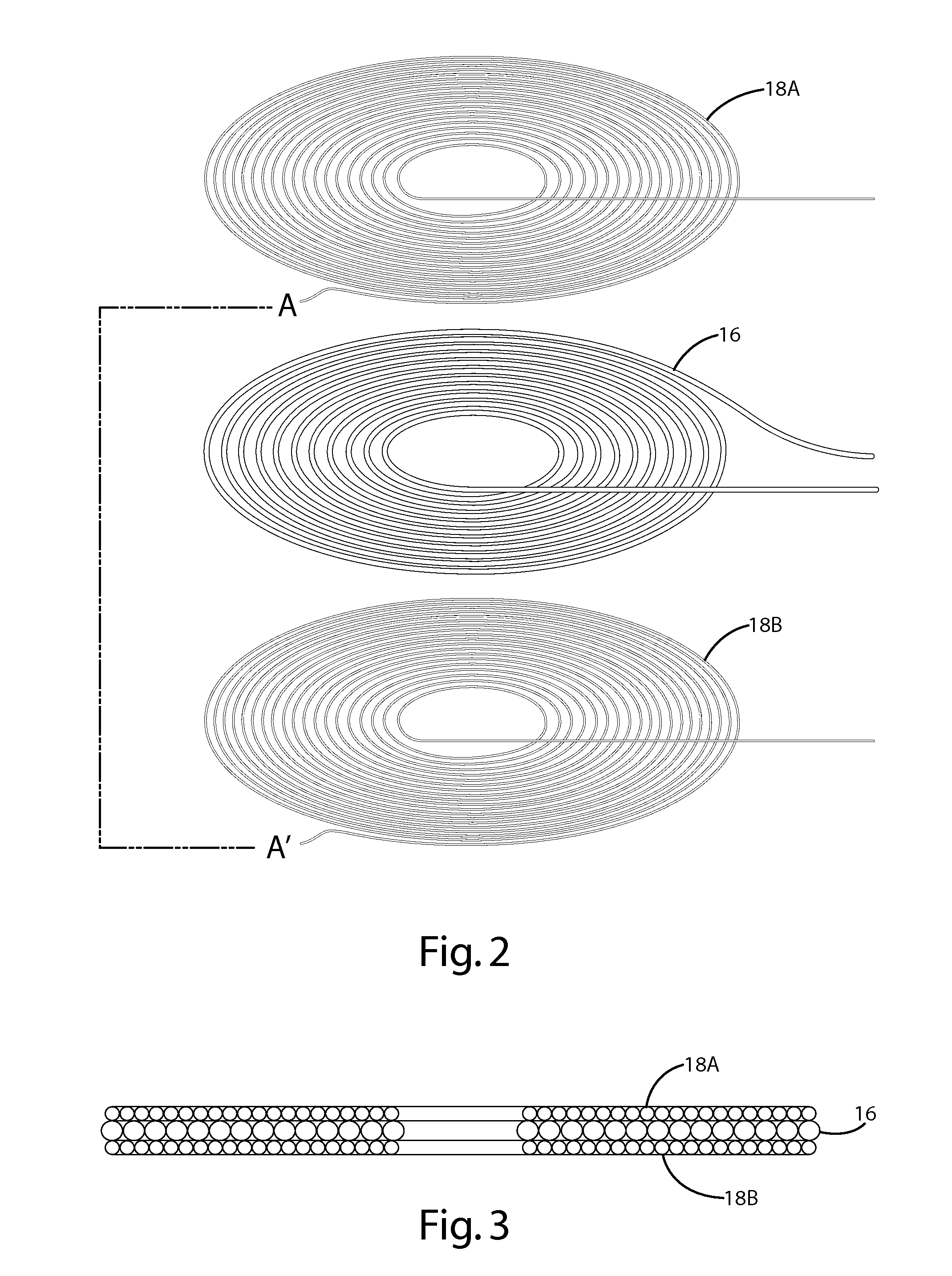
[0037]Referring now to FIG. 1, a diagram of a power supply 10 having an air core transformer 20 in accordance with an embodiment of the present invention is shown. The power supply 10 generally includes a primary-side circuit 12 and a secondary-side circuit 14. As perhaps best shown in FIG. 2, the primary-side circuit 12 includes a primary coil 16 and the secondary-side circuit 14 includes a secondary coil 18. The primary coil 16 and secondary coil 18 cooperate to form a transformer 20. The transformer 20 may be coreless. The primary-side circuit 12 also generally includes a controller 22, a switch driver 24 and switching circuitry 26. The control circuitry 22 controls operation of the switch driver 24, which in turn controls the application of power to the primary coil 16. The secondary-side circuit 14 generally includes a rectifier 28, switching circuitry 30, measurement circuitry 32, isolation circuitry 34 and a switch driver 36. The output of the secondary-side circuit 14 may be...


PUM


Abstract

A power supply to provide electrical power to one or more loads. The power supply may include a resonant air core transformer to provide an adjustable and adaptable source of power to electronic devices. The power supply may include isolated primary-side circuitry and secondary-side circuitry. The primary-side circuitry may include control circuitry that, among other things, provides drive waveforms for the primary-side switching circuitry. In embodiments configured to produce AC output, the secondary-side circuitry may also include switching circuitry. The primary-side control circuitry may provide drive waveforms for the secondary-side switching circuitry. The secondary-side circuitry may include measurement circuitry that measures the current and / or voltage of the output and provides those measurements to the control circuitry through isolation circuitry. The control circuitry may adjust the drive waveforms for the primary-side and / or secondary-side switching circuitry as a function of the measured values.

Description

BACKGROUND OF THE INVENTION[0001]The present invention relates to power supplies and more particularly to a power supply having a transformer for converting mains power into AC or DC power.[0002]A typical power supply includes a transformer. A transformer is an electrical device that transfers electrical energy from a primary coil through a time varying magnetic field to a secondary coil upon the addition of an electrical load to the secondary coil. Transformers are used in a variety of applications, such as mains power delivery for electronics and children's toys, and come in a variety of sizes, from very large to miniature.[0003]A conventional transformer consists of a core, which may be made of iron or some other ferrous material, in the shape of a loop. On one side of the core, wire is coiled around the core, and primary or mains voltage is applied. This side of the core is called the primary. Opposite the primary is a similar arrangement called the secondary. By varying the num...

Claims


Application Information

Patent Timeline
Patent Type & Authority Patents(United States)
IPC IPC(8): H02M3/335H02M5/42
CPCH01F30/08H02M3/33523H02M3/3376H01F27/2804H01F27/2823H01F27/34H01F27/38H01F38/14Y02B70/1433Y02B70/10G05F1/10
Inventor BAARMAN, DAVID W.SCHWANNECKE, JOSHUA K.TAYLOR, JOSHUA B.LORD, JOHN JAMESBACHMAN, WESLEY J.
Owner PHILIPS IP VENTURES BV
Why Eureka
Try Eureka