Method for making a pivot arm assembly for semiconductor wafer handling robots

a technology of semiconductor wafers and robots, which is applied in the direction of arms, manufacturing tools, etc., can solve the problems of contaminating wafers and/or semiconductor chips, affecting the operation of robots, etc., so as to improve the efficiency of use, accurate positioning and rotation, and long operating life

Active Publication Date: 2012-07-24
KAYDON CORP
View PDF12 Cites 0 Cited by
  • Summary
  • Abstract
  • Description
  • Claims
  • Application Information

AI Technical Summary

Benefits of technology

[0008]Another aspect of the present invention provides a pivot arm assembly for semiconductor wafer handling robots and the like that includes an integrally formed thin section bearing to eliminate the fretting associated with prior art bearing arrangements. Preferably, the outside bearing track is formed directly or integrally in the pivot housing, thereby eliminating the separate outer bearing race incorporated into prior art designs, and the associated fretting problems. The pivot arm assembly has a gear segment portion with teeth that are precisely aligned with the bearing tracks so as to accurately locate and rotate the pivot arm assembly during operation. The pivot arm assembly is efficient in use, capable of a long operating life, and particularly well adapted for the proposed use.

Problems solved by technology

Because of the fragile nature of the silicon-based material, and very small thickness of each slice, the wafers can easily be damaged through mishandling.
More specifically, it has been discovered that such bearing mounting arrangements experience infinitesimal small rubbing movement or fretting between the outer races of the bearings and the housing arm recesses, which results in the production of very fine metallic particles or debris that migrates throughout the robot machine thereby causing damage to the moving parts, as well as contaminating the wafers and / or semiconductor chips.
In the event the two ball bearings shown in the prior design of FIG. 1 herein are inadvertently installed backwards or otherwise improperly, even more sever fretting results, which destroys the sterile environment in which semiconductor wafers must be handled.

Method used


Image

  • Method for making a pivot arm assembly for semiconductor wafer handling robots
  • Method for making a pivot arm assembly for semiconductor wafer handling robots
  • Method for making a pivot arm assembly for semiconductor wafer handling robots

Examples


Embodiment Construction

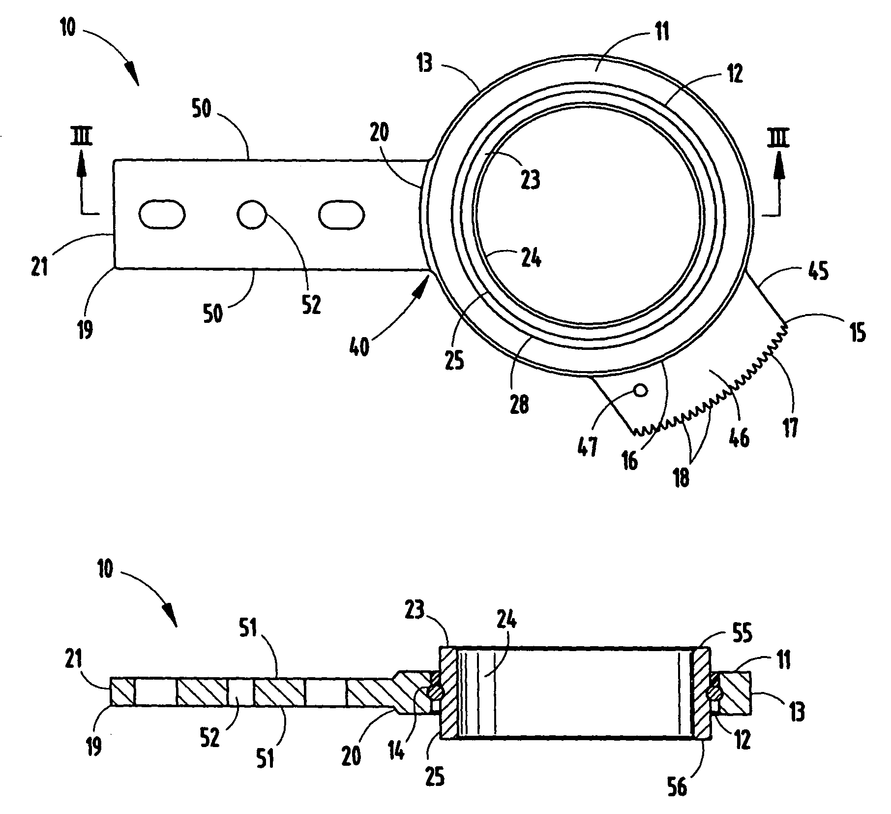
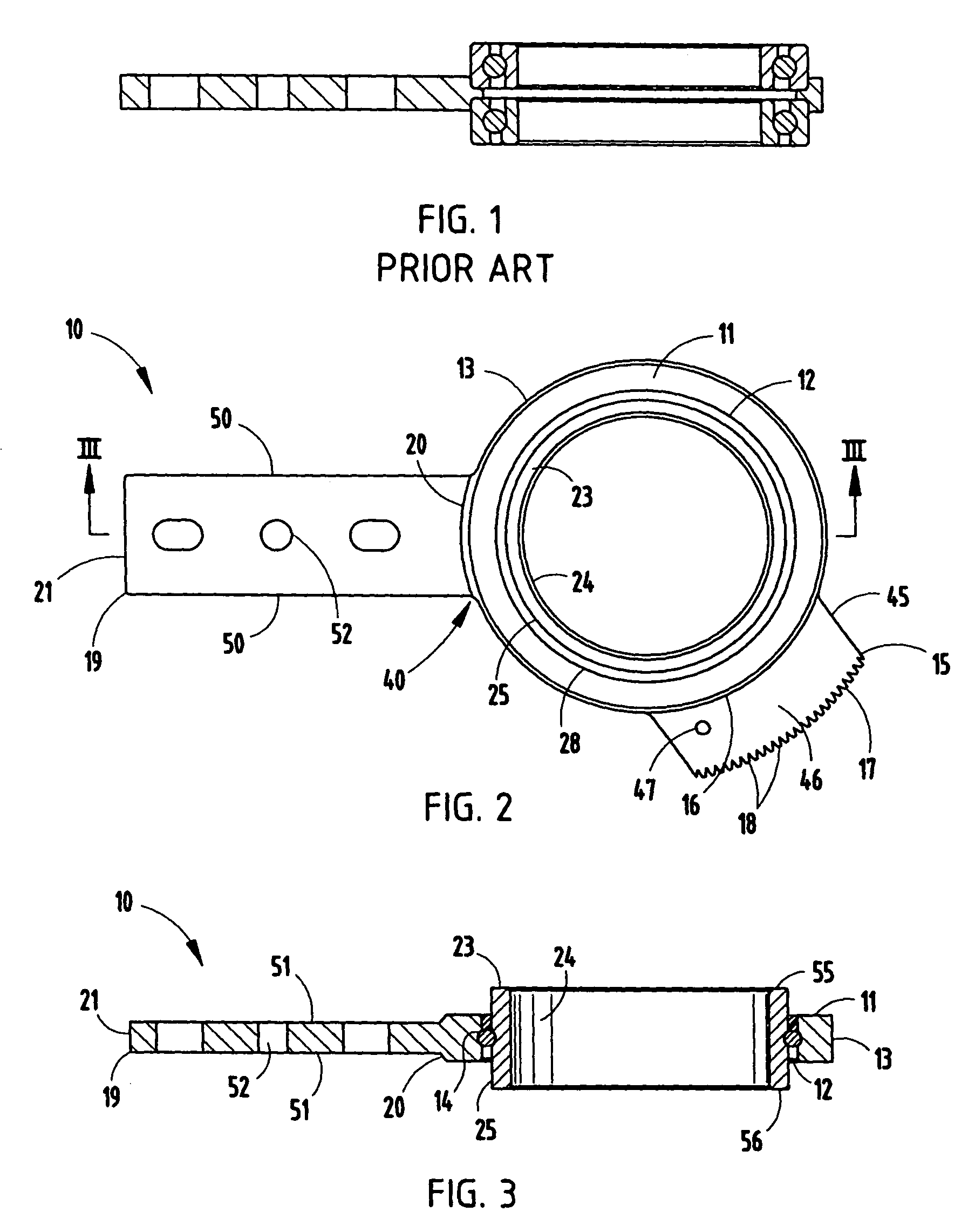
[0040]For purposes of description herein, the terms “upper”, “lower”, “right”, “left”, “rear”, “front”, “vertical”, “horizontal” and derivatives thereof shall relate to the invention as oriented in FIGS. 1 and 2. However, it is to be understood that the invention may assume various alternative orientations and step sequences, except where expressly specified to the contrary. It is also to be understood that the specific devices and processes illustrated in the attached drawings, and described in the following specification, are simply exemplary embodiments of the inventive concepts defined in the appended claims. Hence, specific dimensions and other physical characteristics relating to the embodiments disclosed herein are not to be considered as limiting, unless the claims expressly state otherwise.

[0041]The reference numeral 10 (FIGS. 2 and 3) generally designates a pivot arm assembly for semiconductor wafer handling robots and the like, having an integrally formed bearing construc...


PUM

PropertyMeasurementUnit
thicknessaaaaaaaaaa
contact anglesaaaaaaaaaa
physical characteristicsaaaaaaaaaa

Abstract

A method for making a robot pivot arm assembly includes forming from a rigid, machinable material a circular disk, and forming a circular aperture through the center of the disk. An outer bearing track is formed integrally in the inside surface which defines the aperture, and the apertured disk is positioned in a machining device with a fixturing portion that engages the outer bearing track. An integral outer race, an arm and a gear segment with teeth are then machined into the disk to form the outer portion of the pivot arm assembly. An inner race with an inner bearing track is positioned inside the integral outer race, and rolling bearing elements are inserted into the first and second bearing tracks.

Description

BACKGROUND OF THE INVENTION[0001]The present invention relates to semiconductor wafer handling robots and the like, and in particular to a pivot arm assembly therefor having an integrally formed bearing construction, as well as a method for making the pivot arm assembly.[0002]Semiconductor wafers are typically made from silicon and are used in semiconductor chips and integrated circuit fabrication. Because of the fragile nature of the silicon-based material, and very small thickness of each slice, the wafers can easily be damaged through mishandling. Modern semiconductor processing systems must handle the wafers quickly and accurately in a very sterile environment to prevent contamination or damage to the processed semiconductor wafers and / or assembled chips.[0003]Robots for handling semiconductor wafers and the like are generally well known in the art. Wafer handling robots, such as those disclosed in U.S. Pat. No. 6,817,640 and 2002 / 0182036 to Applied Materials, Inc., typically in...

Claims


Application Information

Patent Timeline
Patent Type & Authority Patents(United States)
IPC IPC(8): B21D53/10B21K1/04
CPCF16C11/04F16C19/50H01L21/67742Y10T29/49684Y10T74/19884Y10T74/19Y10T29/497Y10T29/49Y10T29/49689Y10T29/49696B25J11/0095B25J18/007H01L21/67766
Inventor SCHMIDT, WILLIAM DANIELHANSEN, SCOTT A.CLARY, GREGORY A.DAILEY, DAVID S.
Owner KAYDON CORP
Why Eureka
Try Eureka