Tap and liquid dispenser for a bag-in-box

a liquid dispenser and bag-in-box technology, applied in the direction of liquid dispensers, drinking vessels, packaging under special atmospheric conditions, etc., can solve the problems of poor appearance, difficult dispensing, and unfortunate impression of cheap products, and achieve the effect of producing very inexpensively

Active Publication Date: 2012-07-24
AMKA
View PDF18 Cites 21 Cited by
  • Summary
  • Abstract
  • Description
  • Claims
  • Application Information

AI Technical Summary

Benefits of technology

[0014]Hereby is obtained a tap which initially can be concealed within the bag-in-box with no protruding parts whereby the box can be packed and stored optimally. Further, the tap is easily extractable from within the box without first having to rip the box open, and the tap is easy to operate without the use of any tools and even with thick and clumsy fingers. This makes the tap extremely user-friendly for both elderly and / or handicapped persons. Another advantage of the present invention is that the bag by means of the tap is firmly attached to the box both prior to and during use whereby the risk of damaging the bag or any parts of the tap is minimized. Also the bag is attached in close relation to the box wall ensuring that the bag is not getting wrinkled or folded during the positioning in the box. This also gives a better operational control during tapping when the tap stays firmly in place and does not easily bend or move. The tap is also very advantageous in that it can be used on any standard bag with a standard spout without any fittings needed on the bag or spout. This again ensures that the standard machinery and apparatus for the handling and filling of the bag with a fluid can be used with no costly alterations needed. Yet a further advantage is that the telescope tap consists of very few parts with no complicated details whereby the tap gets very inexpensive to manufacture. Also, because of the gap, the tap is engaged and kept fixed to the box in a very simple way without need for adhesives or other attachment means. The tap (with or without the bag) can simply be slit or guided into a corresponding cut in the box without any cumbersome assembly of the tap onto the box. The design of the tap is also advantageous in that it can be pre-assembled and mounted in the filled bag acting as a plug. The filling can hence be performed on a standard bag with a standard spout using standard filling equipment without any changes. Furthermore, the plugging tap makes the filled bag very easy to handle in the further processing and during the mounting of the bag in a box—for instance by holding onto the spout which is not covered by the tap.
[0015]In other embodiments of the aforementioned telescope tap, the gap is at least partly formed from the base member or from a part of the spout. The first is advantageous in, by very simple means, providing a gap around a part of the tap which can be produced very inexpensively without the need of moving parts in any injection moulding form parts. By the latter embodiment is also obtained that the bag is attached to the box wall as closely as possible with only the spout between the bag and the box wall.
[0016]In an embodiment the knob on the telescope tap is a turning knob connected to the telescope pipe with threads. This yields a very simple way of operating the dispensing unit and controlling the fluid flow.
[0017]In another embodiment the turning knob as described above comprises one or more engagement means engaging with the base member when the tap is in its closed position preventing the knob from being turned. Hereby is achieved that the telescope tap can not be opened by mistake with the tap still in unextracted position and the opening not free of the box.
[0018]In an embodiment the telescope pipe comprises one or more guides engaging with the base member preventing the telescope pipe from rotating in the opening. Hereby is obtained that the telescope tap is kept in position and that, when a person is turning the knob, (s)he is not also rotating the telescope pipe but only the knob opening the tap.
[0019]In another embodiment the telescope tap according to the above further comprises one or more lip contact seals between said base member and said telescope pipe, whereby a watertight connection is ensured.

Problems solved by technology

However, after opening the box usually appears rather deteriorated and with a flawed look yielding an unfortunate impression of a cheap product.
Also, the fastening of the tap in the opening of the box is most frequently very loose and shaky whereby the dispensing becomes more difficult, especially when the bag inside becomes only halfway full.
However, the telescope taps known in the art posses a number of different disadvantages such as taking up a considerably large amount of space within the box, not providing an easy mode of operation for the user, or consisting of a relatively large number of mechanical parts with complicated shapes thereby making the tap rather expensive to manufacture and inappropriate for a disposable product.
One large disadvantage of the construction of this telescope tap is, however, that the tap in its closed position takes up some space within the box whereby the inner bag must be squeezed somewhat together in order to still be able to fit into the box.
Furthermore, when extracted, the pulling force applied to the tap is passed on to the bag which is also pulled towards the box wall resulting in an increased risk for leaks in the seal between the tap and the bag.
This design too, however, takes up quite some space within the box and thus the bag must be made in a special shape in order not to fold or wrinkle around the tap.
Furthermore, the design comprises parts with more complicated shapes such as double pipes and annular cavities which inevitably make the manufacture more expensive.
The bag is then filled through the tap as the final step, which, however, makes the filling process more complicated both with the risks of spilling on the box destroying its appearance and of wearing the assembly of the tap to the box.

Method used


Image

  • Tap and liquid dispenser for a bag-in-box
  • Tap and liquid dispenser for a bag-in-box
  • Tap and liquid dispenser for a bag-in-box

Examples


Embodiment Construction

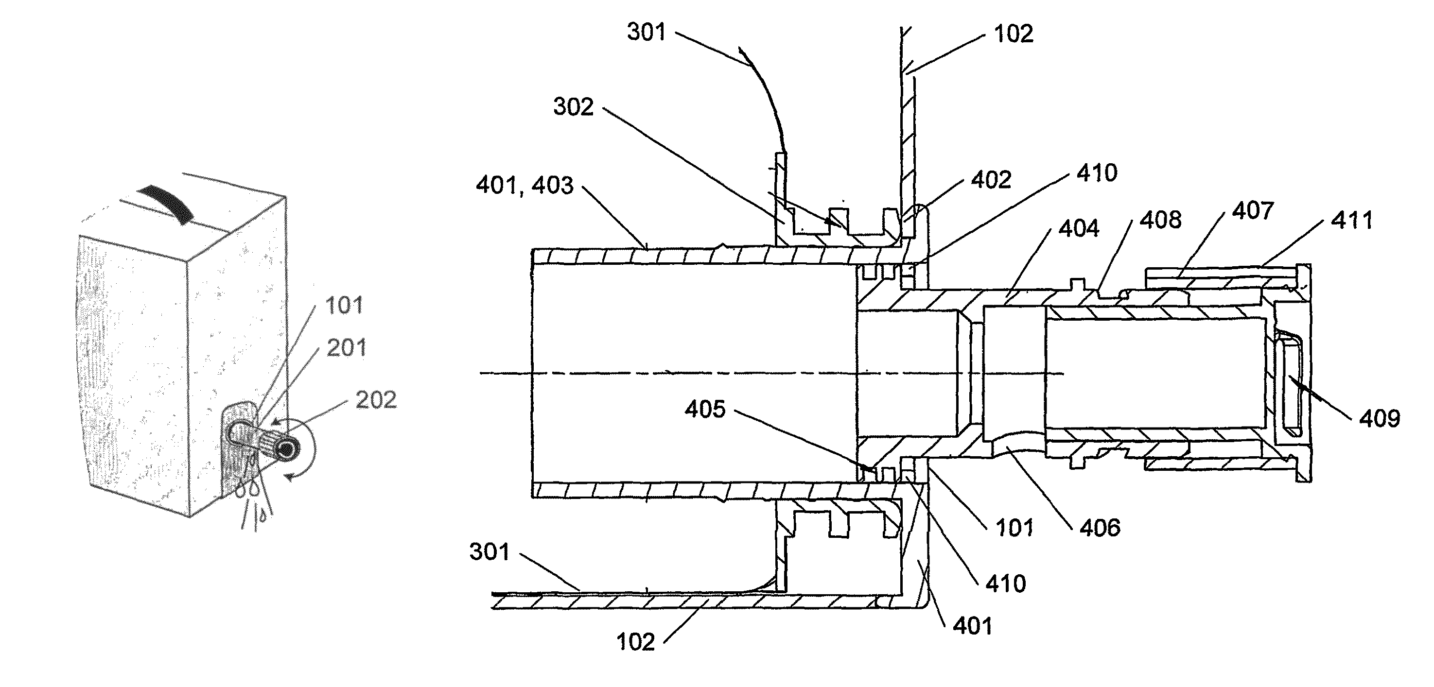
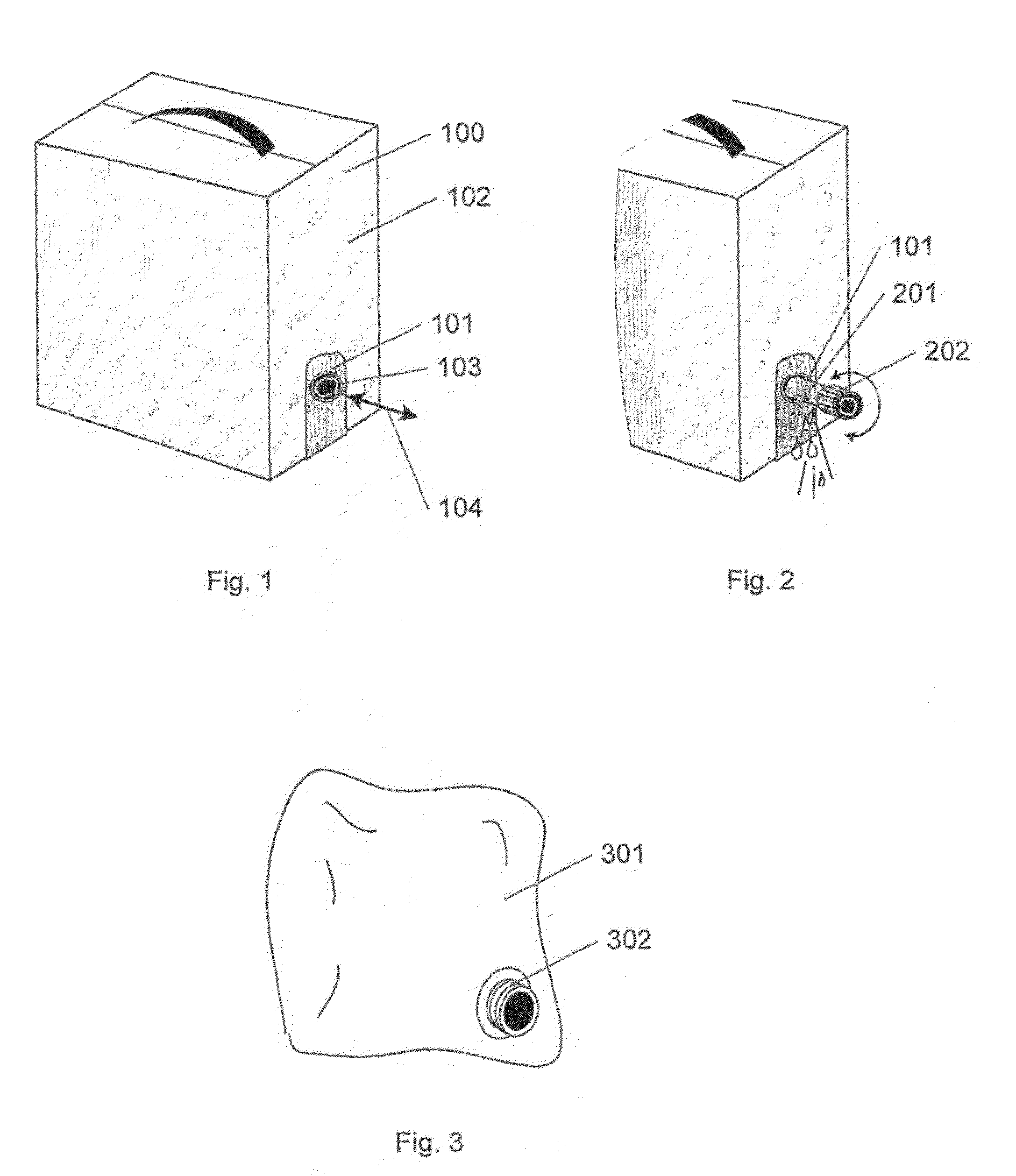
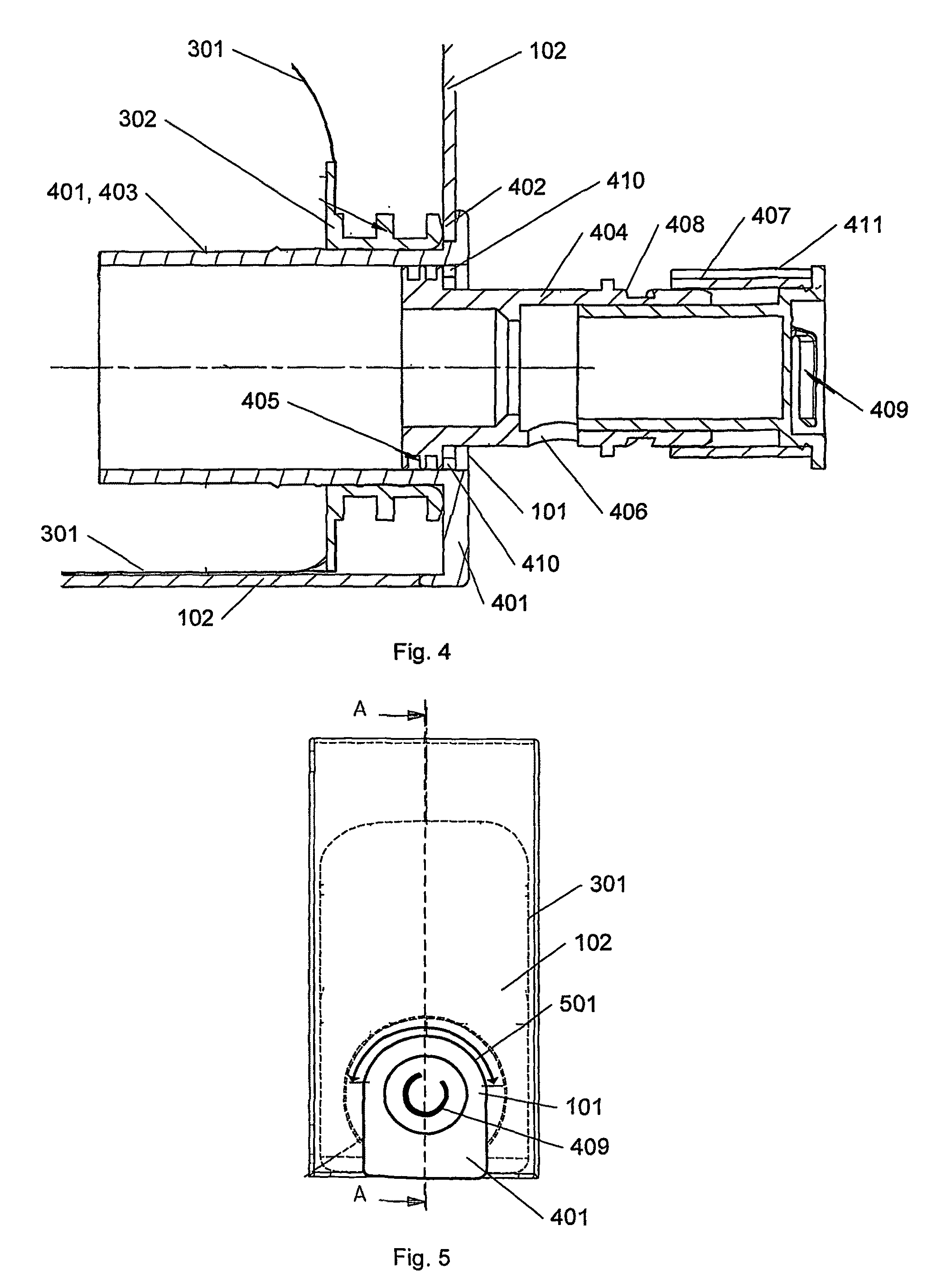
[0040]FIG. 1 shows an example of a bag-in-box 100 for storing a liquid and equipped with a tap 101 according to the invention. The liquid is preferably kept in a flexible bag within the container 102 so that the fluid can be dispensed in small amounts without air getting in contact with the remaining fluid. The box or container 102 can be made of a cardboard material, a plastic or a metal, and can have any shape preferred by the producer. One very big advantage of the tap 101 according to the invention is that it is placed in level with one of the sides of the box 102 with no protruding parts, so that the box can be packed and handled optimally without any risk of damaging any parts and still taking up a minimal amount of space. Furthermore, the tap leaves the design of the exterior of the box as undisturbed as possible with a nice finish.

[0041]The tap is operated by simply pulling in a small ring or handle 103 as illustrated by the arrows 104. Hereby a telescopic pipe 201 extends a...


PUM

PropertyMeasurementUnit
plasticaaaaaaaaaa
flexibleaaaaaaaaaa
timeaaaaaaaaaa

Abstract

This invention relates to a telescope tap to be used for the tapping of liquid from a bag-in-box where a bag containing the liquid and equipped with a spout is placed inside a box. The telescope tap comprises a base member which engages with the spout and with the box wall, a telescope pipe placed sliding extractable in the base member, a handle to extract the telescope pipe from inside the box, a knob for opening and closing the outlet in the telescope pipe, and a gap around a part of the telescope tap for slidably receiving the box wall when sliding the telescope tap into the box. The invention furthermore concerns a method of filling a bag-in-box with a fluid, where a bag with a spout is filled with a fluid, a telescope tap is placed in the spout thereby closing the bag, a cut is made in the box, and the bag then is slid into the box with the tap fitting the cut in the box.

Description

FIELD OF THE INVENTION[0001]The present invention relates to a tap and liquid dispensing unit for a bag-in-box. The invention furthermore relates to a method to fill a liquid into a bag-in-box from which the liquid is ready to be tapped in smaller amounts.BACKGROUND[0002]Liquids are often stored and sold in boxes or containers which facilitate a compact packing and easy handling of the liquid. By storing the fluid in a flexible bag within the box—a so-called bag-in-box—any amount of the liquid can be tapped from the container without air getting in contact with the liquid. This is advantageous for instance when tapping wine, as a consumer in this way is given the opportunity to enjoy a single glass of wine from the bag-in-box without the remainder of the wine in the container having to be used within a limited time in order to taste the best.[0003]Usually the tap or dispenser on a bag-in-box is initially concealed within the box so that the boxes can be packed and stored as compactl...

Claims


Application Information

Patent Timeline
Patent Type & Authority Patents(United States)
IPC IPC(8): A47G19/22
CPCB67D3/045B65D77/067Y10S383/906
Inventor NIELSEN, LAUDIGE, ERIK
Owner AMKA
Why Eureka
Try Eureka