Controller of multi-phase electric motor

a multi-phase electric motor and control device technology, applied in the direction of electronic commutators, dynamo-electric converter control, dynamo-electric gear control, etc., can solve the problems of giving the user an unpleasant feeling, a/d converter cannot detect the accurate current value of each phase, and the measurement of an accurate current value by a current detector cannot be carried out during such a period, so as to prevent the generation of noise based on current ripple and accurately detect the

Active Publication Date: 2012-07-24
OMRON AUTOMOTIVE ELECTRONICS CO LTD
View PDF27 Cites 13 Cited by
  • Summary
  • Abstract
  • Description
  • Claims
  • Application Information

AI Technical Summary

Benefits of technology

[0026]One or more embodiments of the present invention provides a controller of a multi-phase electric motor capable of detecting the current value of each phase at satisfactory precision for every control period using a single current detection section, and preventing the generation of noise arising from the current ripple involved in the change in the PWM signal.
[0028]Thus, the phase movement section moves the PWM signal of the predetermined phase by gradually changing the movement amount of the phase in one control period, and outputs the PWM signal which phase is moved to the drive section, and thus sudden change in current by the change in the PWM signal can be suppressed, and generation of noise based on the current ripple can be prevented. Furthermore, even if the time interval of switching between the predetermined phase and another phase is originally short to an extent the current value cannot be detected, the time interval of the switching between the predetermined phase in which the phase is moved and the another phase becomes large, and the current value can be detected with the current value of the moved predetermined phase stabilized, whereby the current value of each phase can be accurately detected for every control period using the single current detection section without changing the duty of each phase.
[0030]Thus, when the movement amount of the phase of the predetermined phase in the control period immediately before and the movement amount of the phase of the predetermined phase in the relevant control period are different, the movement amount of the phase in one control period is gradually changed from the movement amount immediately before, and thus the sudden change in current by the change of the PWM signal is suppressed, and generation of noise based on the current ripple can be prevented.
[0032]Thus, even if the time interval of switching between the predetermined phase and another phase is originally short to an extent the current value cannot be detected, the time interval of the switching between the predetermined phase in which the phase is moved and the another phase becomes large, and the current value can be detected with the current value of the moved predetermined phase stabilized, whereby the current value of each phase can be accurately detected for every control period using the single current detection section without changing the duty of each phase.
[0034]Thus, the time interval of the switching between the predetermined phase and another phase is the largest in the last period of the control period, and the current value can be detected in a state that the current value is stabilized without barely any influence of the switching noise immediately before the time in which the PWM signal of the predetermined phase is changed, whereby the current value of each phase can be accurately detected for every control period using the single current detection section without changing the duty of each phase.
[0035]According to the controller of the multi-phase electric motor according to one or more embodiments of the present invention, the phase movement section moves the PWM signal of the predetermined phase by gradually changing the movement amount of the phase in one control period, and outputs the PWM signal which phase is moved to the drive section, and thus sudden change in current by the change of the PWM signal can be suppressed, and generation of noise based on the current ripple can be prevented. Furthermore, even if the time interval of the switching between the predetermined phase and another phase is originally short to an extent the current value cannot be detected, the time interval of the switching between the predetermined phase in which the phase is moved and the another phase becomes large, and thus the current value can be detected with the current value of the moved predetermined phase stabilized, whereby the current value of each phase can be accurately detected for every control period using the single current detection section without changing the duty of each phase.

Problems solved by technology

In this time, since the current is not stable due to the switching time of an electric field effect transistor of the drive circuit, the presence of dead zone (dead time), and also the response delay of an electronic processing circuit, the measurement of an accurate current value by a current detector cannot be carried out during such a period.
If the input signal is not stably inputted continuously for 2 μs, the A / D converter cannot detect an accurate current value of each phase.
However, if the frequency of the ON / OFF of the switching element for driving the multi-phase electric motor is included in an audible frequency as a result of performing the shift correction, it is heard by the user as noise and gives the user an unpleasant feeling.
If the frequency of the current ripple is included in the audible region, it is heard by the user as noise and gives the user an unpleasant feeling.
That is, the noise is generated when having the control cycle time of between 50 μs and 50 ms.
However, there is not yet proposed a controller of a multi-phase electric motor capable of generating the PWM signal based on the saw-tooth signal or the triangular signal, and detecting the current value of each phase at satisfactory precision for every control period using a signal current detection section, and having a sufficient noise prevention effect.
With the sudden current fluctuation, noise based on the current ripple generates from the motor.

Method used


Image

  • Controller of multi-phase electric motor
  • Controller of multi-phase electric motor
  • Controller of multi-phase electric motor

Examples


Embodiment Construction

[0044]Embodiments of the present invention will be described below with reference to the drawings.

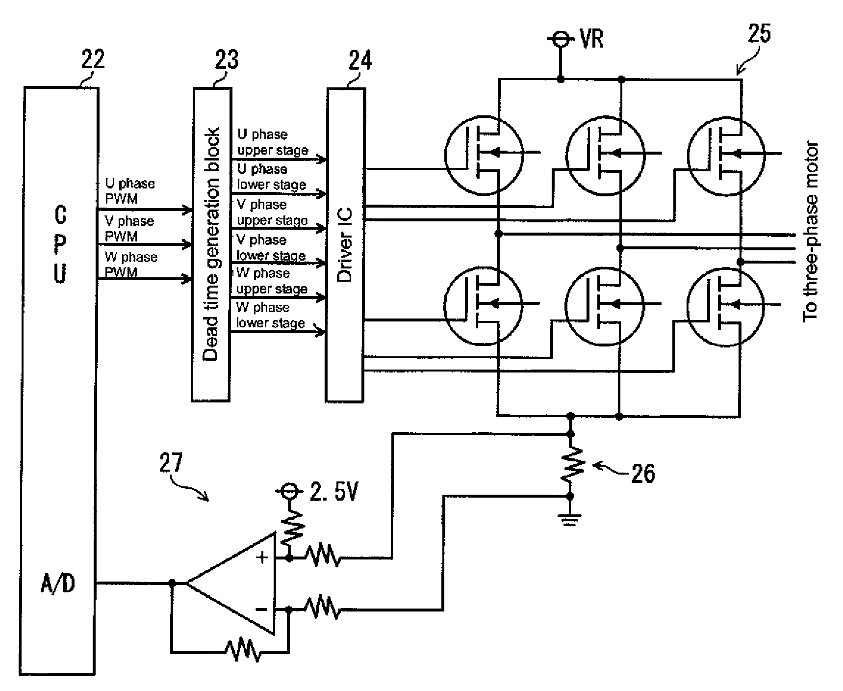
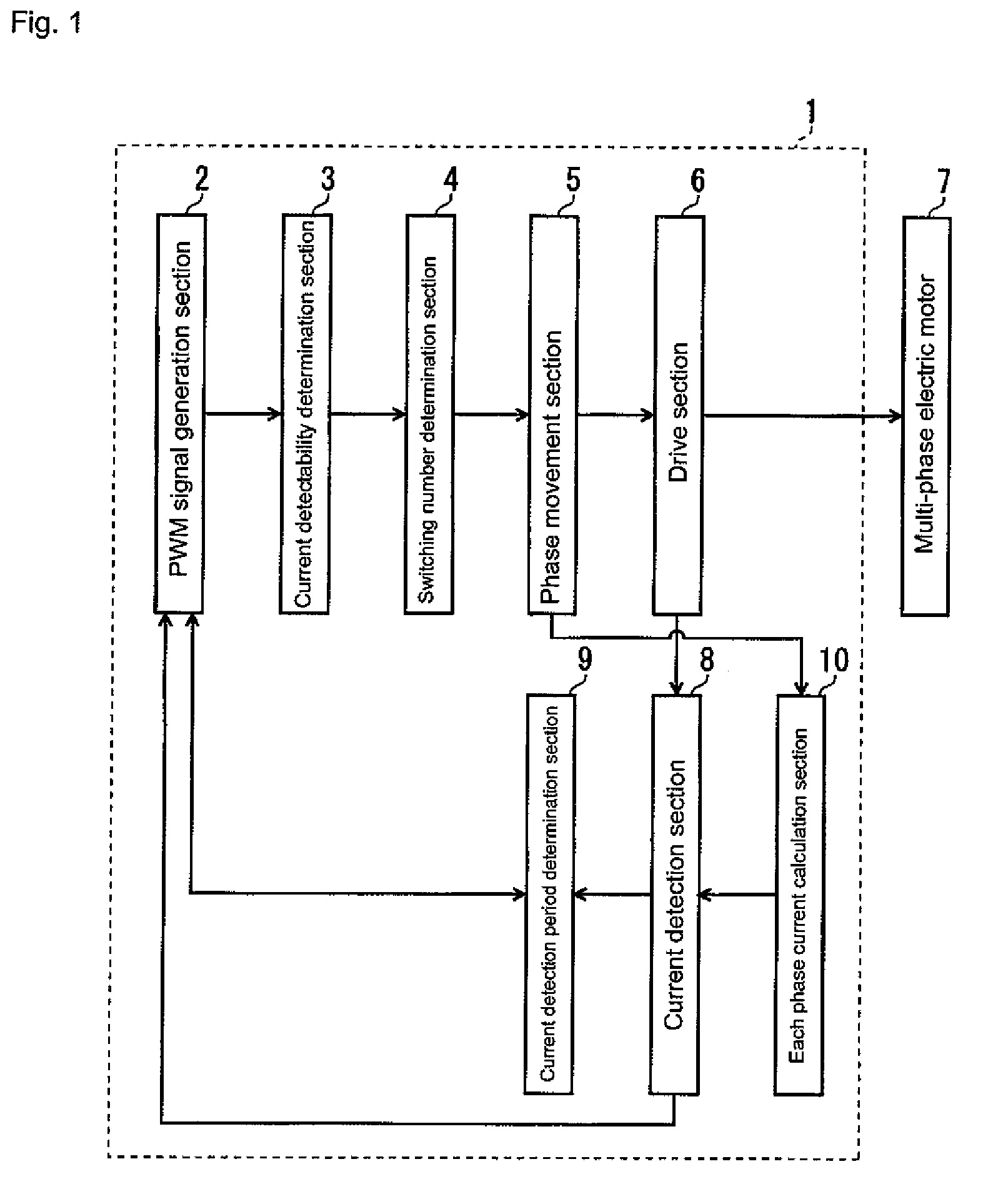
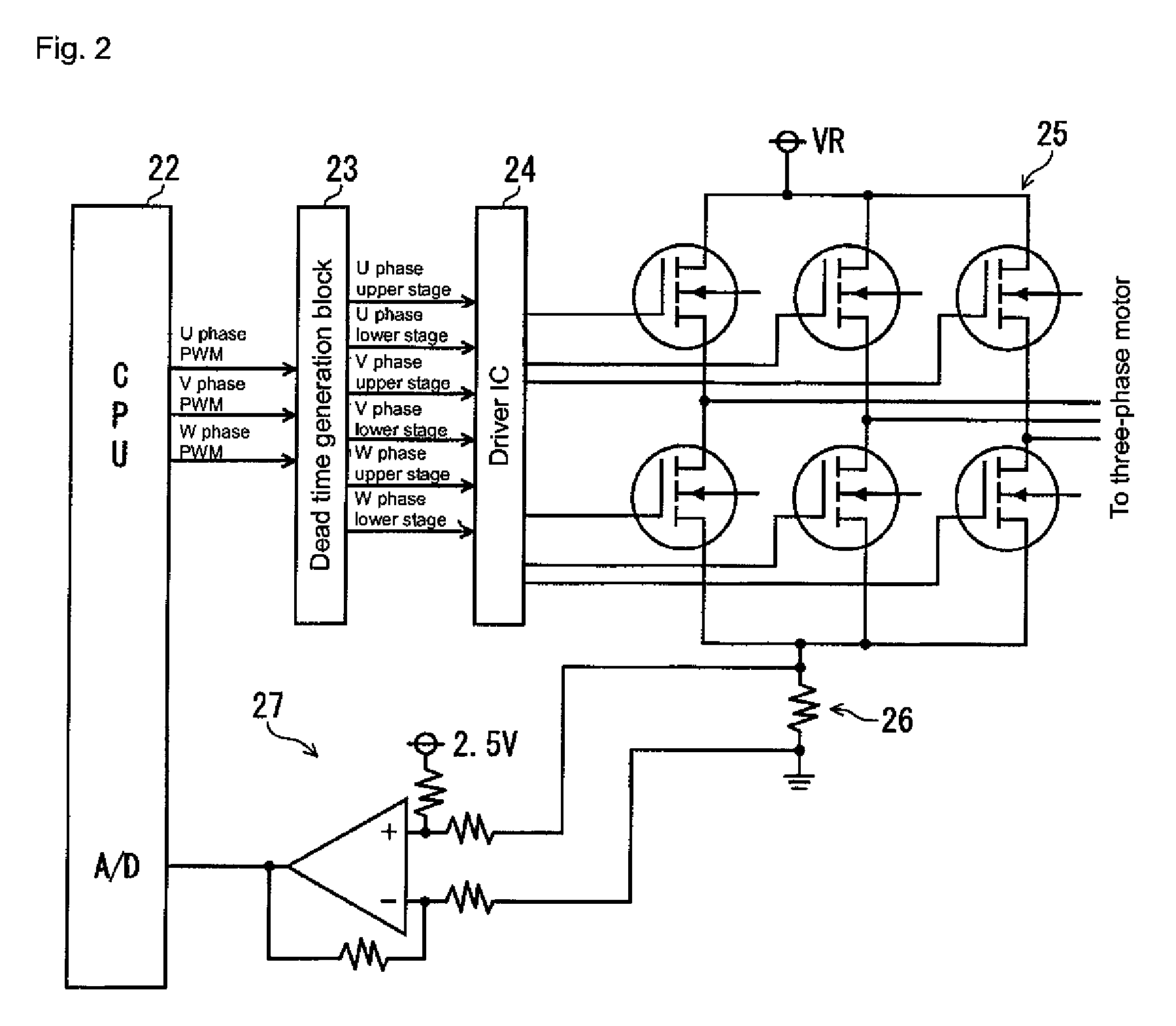
[0045]FIG. 1 shows a block diagram of a controller of a multi-phase electric motor according to one or more embodiments of the present invention. A controller 1 of a multi-phase electric motor 7 according to one or more embodiments of the present invention has the following configuration. A drive section 6 is connected between a power supply and a ground, as hereinafter described in the description of a circuit diagram of FIG. 2, includes a pair of upper arm switching elements and lower arm switching elements, and drives the multi-phase electric motor 7. A current detection section 8 is connected between the drive section 6 and a ground, and detects a current value flowing to the multi-phase electric motor 7 at a predetermined time. A PWM signal generation section 2 generates PWM signal of each phase based on the current value detected in the current detection section 8 and the saw-toot...


PUM


Abstract

A controller of a multi-phase electric motor has a drive section having an upper arm switching element and a lower arm switching element for driving the multi-phase electric motor, a single current detection section for detecting a current value of the multi-phase electric motor, a pulse width modulation signal generation section for generating plural pulse width modulation of each phase within one control period based on the current value detected by the current detection section and a carrier signal, and a phase movement section for moving the pulse width modulation signal of a predetermined phase generated by the pulse width modulation signal generation section by gradually changing a movement amount of the phase in one control period, and outputting the resultant pulse width modulation signal to the drive section.

Description

BACKGROUND OF THE INVENTION[0001]1. Technical Field[0002]The present invention relates to a pulse width modulation (PWM) drive control of a multi-phase electric motor such as a three-phase brushless motor. In particular, the present invention relates to a noise prevention technique of a controller of a multi-phase electric motor arranged with a single current detector between a drive circuit for PWM driving and a direct current (DC) power supply (high voltage side or low voltage side).[0003]2. Related Art[0004]In a controller for driving a multi-phase electric motor such as a three-phase brushless motor, a PWM signal for determining ON / OFF timing of a switching element for driving the multi-phase electric motor is generated by comparing a carrier wave of saw-tooth shape or triangular shape (saw-tooth signal, triangular signal) and a duty set value corresponding to a target current value in each phase of the multi-phase electric motor. That is, whether the PWM signal is high level or...

Claims


Application Information

Patent Timeline
Patent Type & Authority Patents(United States)
IPC IPC(8): H02P6/16H02P21/00H02M1/14H02H5/04H02H1/00H02P27/00G05B11/28H02P6/08H02P6/06H02P6/15H02P6/28
CPCH02M7/53875H02P27/08H02P29/0038H02M2001/0009H02M7/5395H02P29/50H02M1/0009
Inventor HAMASAKI, MASAMITSUKURATANI, SHINICHINAKAMURA, TAKENOBU
Owner OMRON AUTOMOTIVE ELECTRONICS CO LTD
Why Eureka
Try Eureka