Cuvette for flow-type particle analyzer

a flow-type particle analyzer and cuvette technology, applied in the field of fluid stream optical analysis, can solve the problems of time-consuming and difficult, and achieve the effects of facilitating use with excitation and detection optics, minimizing vibration of the flow cell or cuvette, and facilitating positioning the cuv

Active Publication Date: 2012-07-31
BECTON DICKINSON & CO
View PDF25 Cites 131 Cited by
  • Summary
  • Abstract
  • Description
  • Claims
  • Application Information

AI Technical Summary

Benefits of technology

[0013]An advantage of the present invention is that the cuvette can be mounted in the instrument in a fixed position and coupled directly to the excitation and / or detection optics, and the flow tube can be replaced conveniently without disturbing the alignment of the optics with the cuvette.
[0014]The cuvette of the present invention, having a replaceable flow tube, can be adapted for use in a sorting flow cytometer. A sorting flow cytometer includes a droplet generator, such as a piezo-electric oscillator, that applies a vibratory force, directly or indirectly, to the fluid sample stream and causes the fluid sample stream to break into droplets after leaving the flow channel. In some embodiments, the droplet generator is adapted to indirectly impart oscillating pressure waves to the sample stream by vibrating an element on the flow cell or flow tube. In other embodiments, the droplet generator is adapted to impart a vibratory force directly to the sample stream, thereby minimizing vibrations of the flow cell or cuvette.
[0015]In one embodiment, the cuvette and the flow cell chamber are not directly coupled together, and the oscillator is adapted to apply a vibratory force to the flow cell chamber or to the flow tube. Preferably, the oscillations are along the flow channel axis. Because the flow tube is movable within the sleeve channel of the cuvette, vibrations of the flow cell are largely isolated from the optical cuvette and do not interfere with the stability of the excitation and / or detection optics. Additionally, vibrations applied to the flow tube can be isolated from the flow cell chamber, or vice versa, by using a connector between the flow tube and the flow cell chamber that allows independent movement of the flow tube.
[0016]In another embodiment, the droplet generator is adapted to apply oscillating forces that are radial to the axis of the flow tube. The oscillator can be a piezoelectric crystal in the shape of a ring surrounding the outside of the flow tube, operating in a radial mode. The piezoelectric ring operating in a radial mode about the flow tube alternately compresses and releases the outer surface of the nozzle tubing, sufficient to set up regular oscillations on the surface of the sheathed sample stream. A droplet generator using a piezoelectric oscillator that applies radial, compressive oscillations is described in U.S. Pat. No. 6,070,973, incorporated herein by reference. The use in a sorting flow cytometry of a piezoelectric ring operating in a radial mode to provide a vibratory force to the fluid stream is described in U.S. Patent Application Publication No. US 2007 / 0269348, incorporated herein by reference.
[0017]In preferred embodiments, the cuvette will have flat external surfaces to facilitate use with the excitation and detection optics. Optical elements, such as a lens or minor, can be joined to the cuvette or molded as part of the cuvette block (see, for example, WO 01 / 27590, incorporated herein by reference). The cuvette may also contain additional features that facilitate positioning the cuvette.
[0018]In some embodiments, the flow channel within the flow tube has a rectangular cross-sectional shape. In order to fix the orientation of the flow channel relative to the excitation and detection optics, the flow tube and / or the cuvette will include a means to prevent rotation of the flow tube around the axis of the flow channel. In one embodiment, the flow tube will have a flat key or slot that facilitates positioning the flow tube in a precise angular position. Alternatively, the flow tube and sleeve channel can have cross-sectional shapes that prevent rotation of the flow tube around the flow channel axis. In some applications, it may be desirable to include a rotational position adjusting mechanism to insure the desired rotational position of the flow tube with respect to the cuvette and optics.

Problems solved by technology

Replacement of the components of the fluidic path typically requires realignment of the excitation and detection optics, which is both time-consuming and difficult.

Method used


Image

  • Cuvette for flow-type particle analyzer
  • Cuvette for flow-type particle analyzer
  • Cuvette for flow-type particle analyzer

Examples


example 1

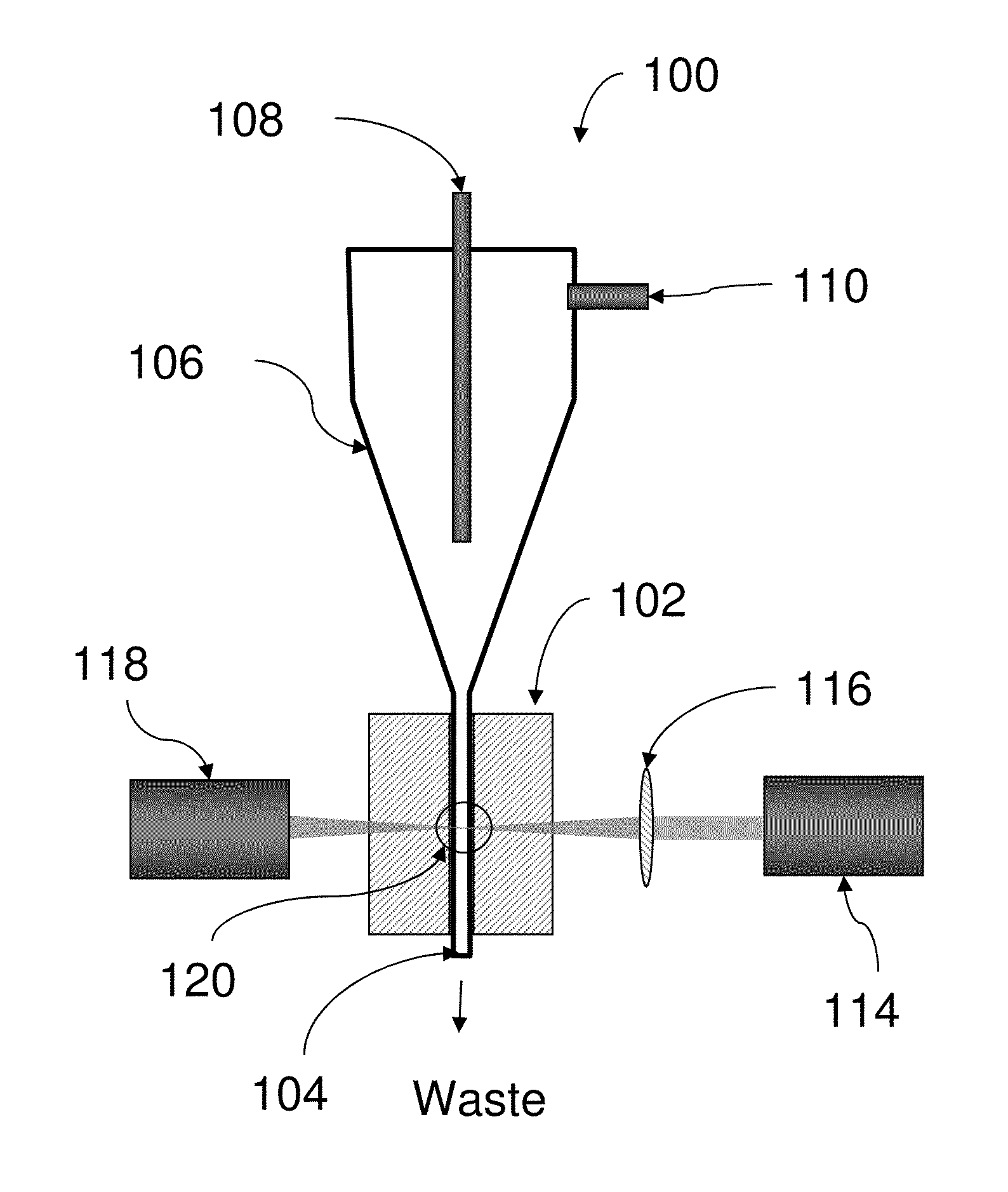
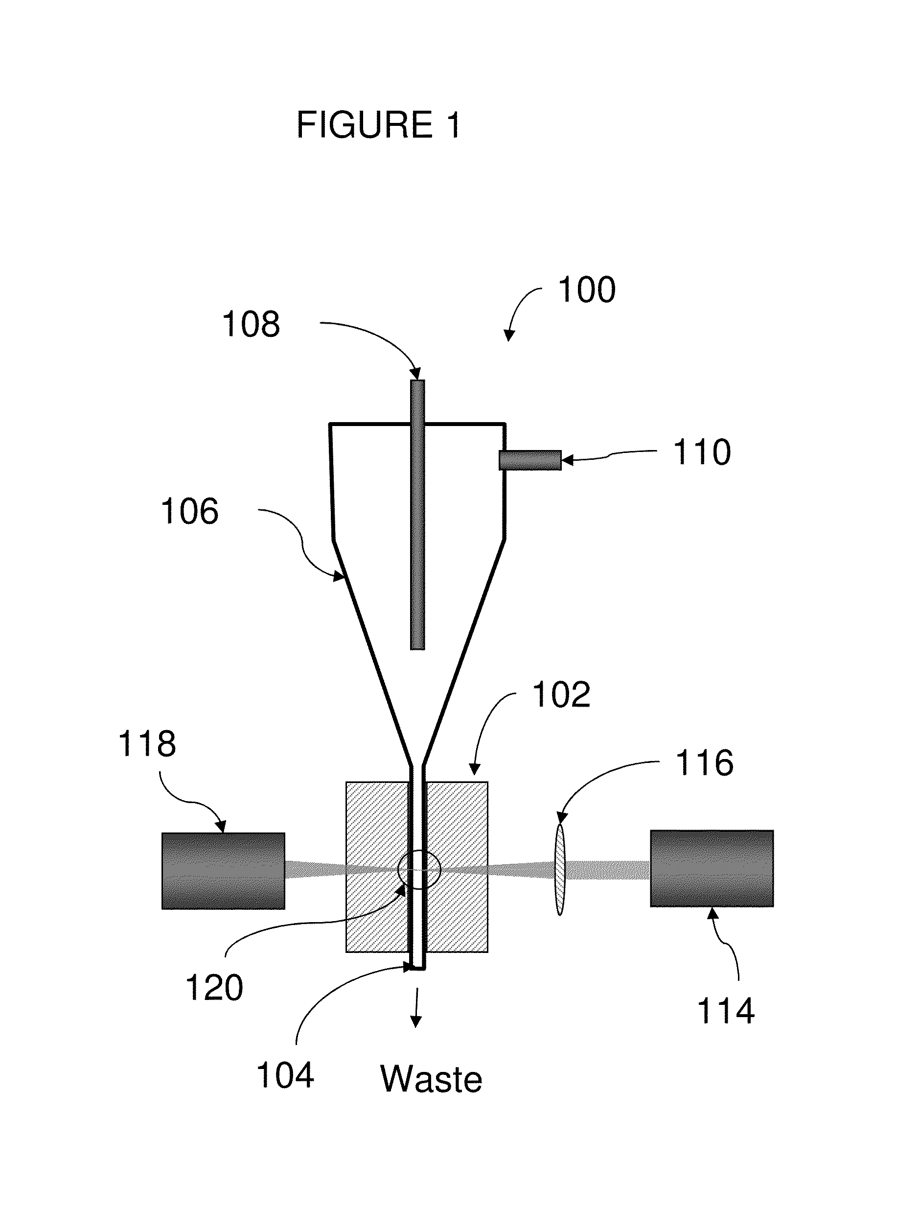
Cuvette for use in a Sorting Flow Cytometer

[0054]A flow cell and cuvette essentially as shown in FIG. 5 and described, above, was constructed using standard optical components commercially available for use in the telecommunication and photonics industries.

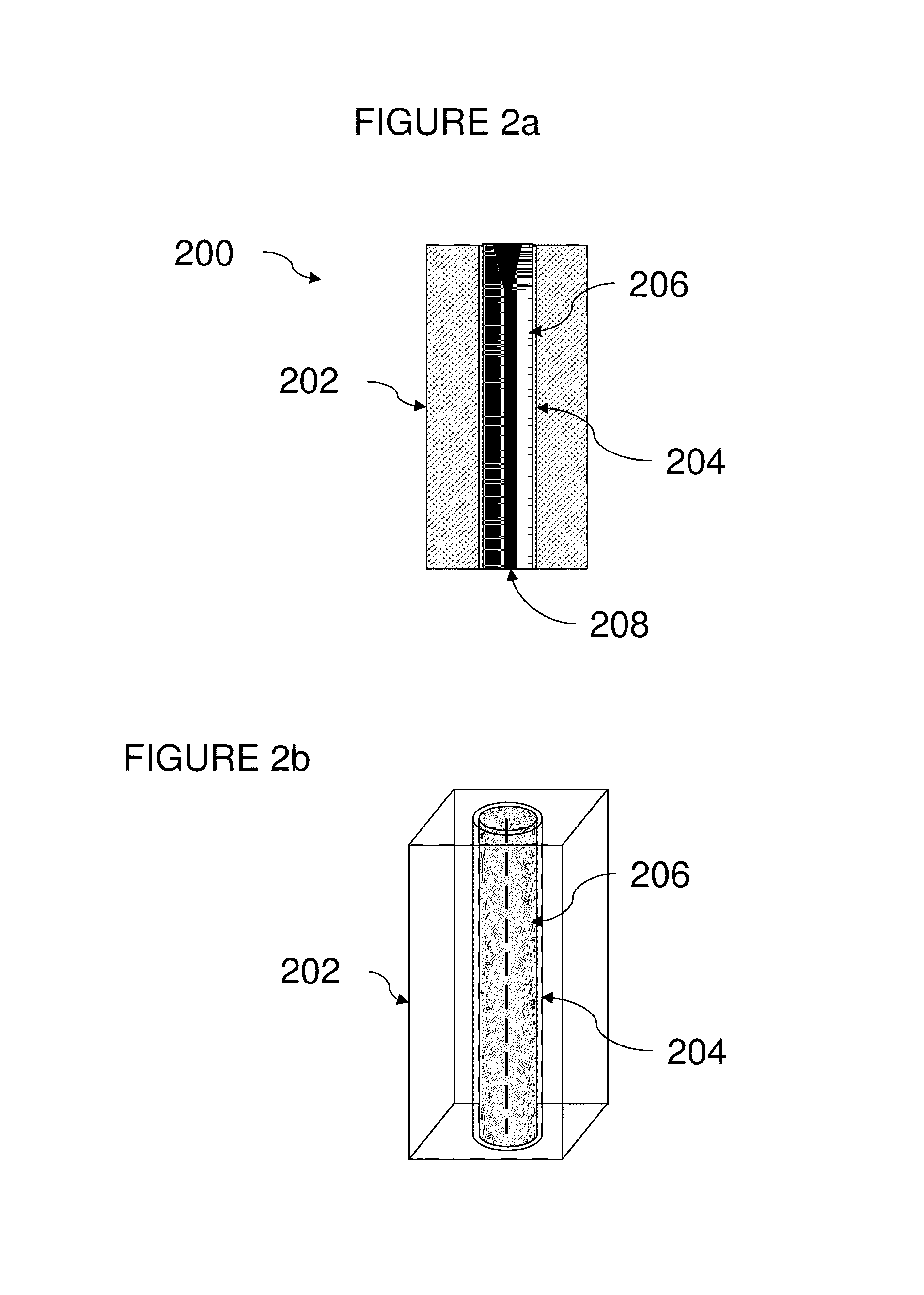
[0055]A fiber optic ferrule with a rectangular core 127 μm×254 μm was used the flow tube. A fiber optic collimator sleeve designed for use with the ferrule was used as the sleeve tube. The ferrule fitted into the collimator sleeve such that the gap between the ferrule and the collimator sleeve was less than 5 μm. The gap was filled with index-matching fluid using capillary effect. The index-matching fluid also functioned as a lubricant to facilitate the insertion and removal of the ferrule into the sleeve.

[0056]The cuvette block was constructed from borosilicate glass tubing having a rectangular cross-section. Plastic covers on the top and bottom, each having a central hole sized to fit the sleeve tube, were glued to each end of t...


PUM

PropertyMeasurementUnit
diameteraaaaaaaaaa
lengthsaaaaaaaaaa
indices of refractionaaaaaaaaaa

Abstract

The present invention provides an optical cuvette for use in a flow-type particle analyzer, wherein the cuvette includes a removable flow tube containing a flow channel oriented coaxially.

Description

BACKGROUND OF THE INVENTION[0001]1. Field of the Invention[0002]The present invention relates to the field of optical analysis of fluid streams and, in particular, to flow-type particle analyzers, such as flow cytometers, and particle sorting systems.[0003]2. Description of Related Art[0004]Flow-type particle analyzers, such as flow cytometers, are well known analytical tools that enable the characterization of particles in a fluid stream on the basis of optical parameters such as light scatter and fluorescence. In a flow cytometer, particles such as molecules, analyte-bound beads, or individual cells in a fluid suspension are passed by one or more detectors in which the particles are exposed to an excitation light, typically from one or more lasers, and the light scattering and fluorescence properties of the particles are measured. Each particle, or subcomponents thereof, may be labeled with a multiplicity of spectrally distinct fluorescent dyes. Typically, detection or characteriz...

Claims


Application Information

Patent Timeline
Patent Type & Authority Patents(United States)
IPC IPC(8): G01N1/10
CPCG01N15/1434G01N21/05G01N2015/149G01N2021/0346
Inventor CHEN, YONG QIN
Owner BECTON DICKINSON & CO
Why Eureka
Try Eureka