Method for manufacturing resin-layer coated toner, resin-layer coated toner, developer, developing apparatus and image forming apparatus

a technology of coating toner and coating layer, which is applied in the direction of electrographic process apparatus, instruments, developers, etc., can solve the problems of reducing lowering the drying speed of liquid substances, and lowering the yield of coating particles, so as to achieve excellent image quality and stable formation

Active Publication Date: 2012-08-07
SHARP KK
View PDF10 Cites 7 Cited by
  • Summary
  • Abstract
  • Description
  • Claims
  • Application Information

AI Technical Summary

Benefits of technology

[0015]When the liquid substance to plasticize the toner base particles and the fine resin particles is sprayed by carrier gas from the spraying section including the two-fluid nozzle, the liquid substance plasticizes the toner base particles and the fine resin particles and is gasified in the apparatus. By stirring the toner base particles and the fine resin particles plasticized by the liquid substance in the apparatus, the fine resin particles form a resin layer on the surface of the toner base particles so that a resin-layer coated toner is obtained. In such a method for manufacturing the resin-layer coated toner, the carrier gas is introduced from the spraying section and is fluidized by the circulating section to keep the pressure in the apparatus high and the carrier gas including the gasified substance (hereinafter, also referred to as “carrier gas including gasified substance”) is exhausted to the outside of the powder passage through the exhausting section, when pressure P1 in the powder passage and pressure P0 outside the powder passage satisfy the above-described formula (1), it is thus possible to stably exhaust the carrier gas including gasified substance, allowing the fluidized state of the toner base particles and the fine resin particles to be maintained. Furthermore, it is possible to suppress generation of coarse particles due to a reduced drying speed of the liquid, and to prevent the toner base particles and the fine resin particles from adhering to an inner wall of the powder passage to aggregate and grow. Accordingly, it is possible to obtain the resin-layer coated toner having a small coarse-particle content and excellent film quality with high yield.
[0033]According to the invention, the image forming apparatus includes a developing apparatus of the invention. By forming an image with such an image forming apparatus, it is possible to stably form an image that is highly-defined without density unevenness and excellent in image quality.

Problems solved by technology

However, the method disclosed in Japanese Examined Patent Publication JP-B2 5-10971 (1993) causes following problems.
Accordingly, the gasified substance needs to be exhausted to the outside of the powder passage, and without exhausting the gasified substance to the outside, a drying speed of the liquid substance is reduced, thus the powder particles in which an undried liquid substance is remained adhere to other powder particles to generate an aggregate of the powder particles, which causes a problem of the lowered yield of the coating particles.
When the powder particles and the coating materials aggregate and grow on the inner wall of the apparatus, there causes a problem that the passage for the powder particles to flow becomes narrow enough to prevent isolated flowing of the powder particles, as well as a problem of the lowered yield of the coating particles.
It is impossible to solve such problems without stably exhausting the gasified substance to the outside of the powder passage.

Method used


Image

  • Method for manufacturing resin-layer coated toner, resin-layer coated toner, developer, developing apparatus and image forming apparatus
  • Method for manufacturing resin-layer coated toner, resin-layer coated toner, developer, developing apparatus and image forming apparatus
  • Method for manufacturing resin-layer coated toner, resin-layer coated toner, developer, developing apparatus and image forming apparatus

Examples


example 1

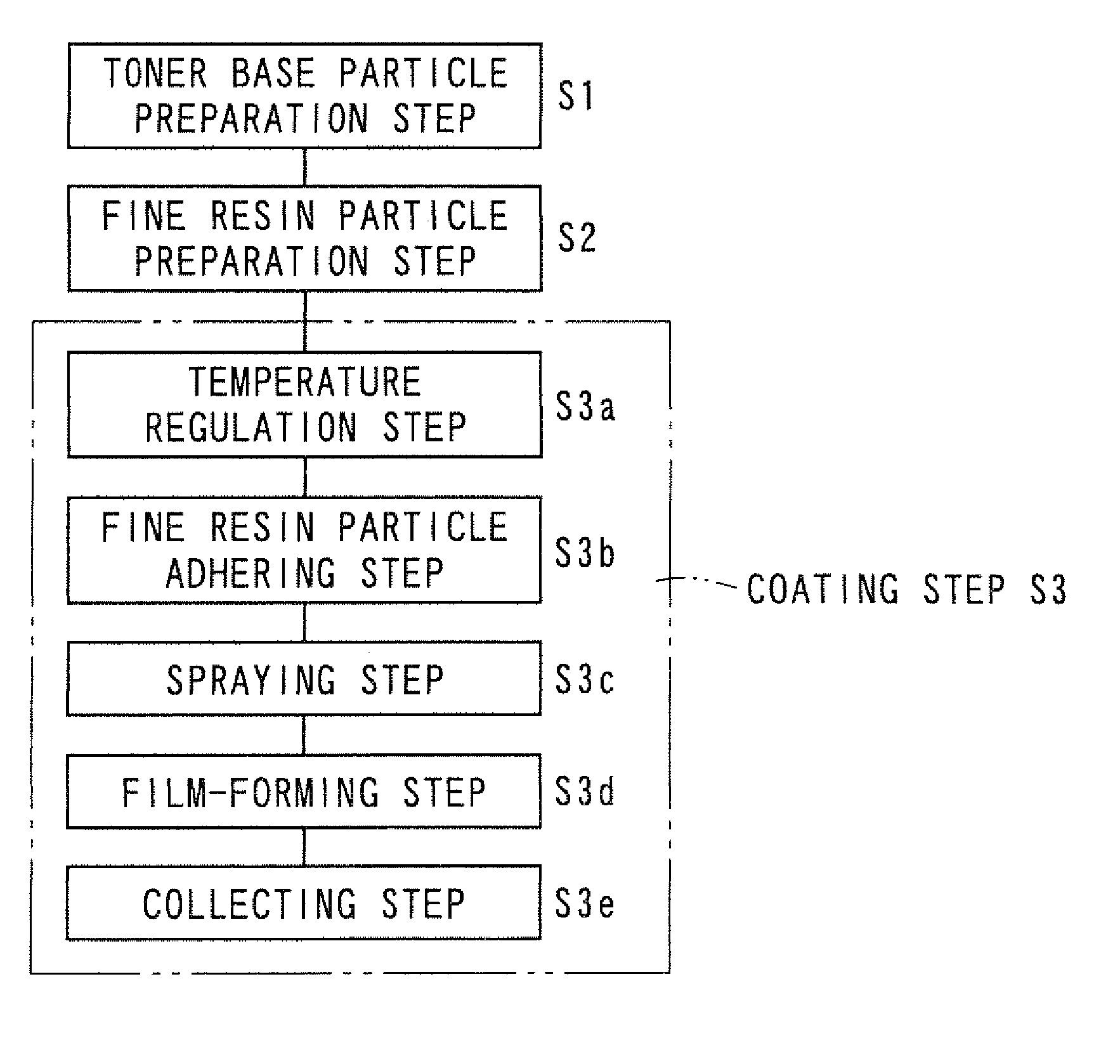
[0192][Toner Base Particle Preparation Step S1]

[0193]Raw materials of the toner base particles and addition amounts thereof were as follows:

[0194]

Polyester resin (trade name: DIACRON, manufac-87.5% (100 parts) tured by Mitsubishi Rayon Co., Ltd., glasstransition temperature of 55° C., softeningtemperature of 130° C.)C.I. Pigment Blue 15:35.0% (5.7 parts)Release agent (Carunauba Wax, melting point6.0% (6.9 parts)of 82° C.)Charge control agent (tradename: Bontron E84,1.5% (1.7 parts)manufactured by Orient Chemical Industries, Ltd.)

[0195]After pre-mixing each of the constituent materials described above by a Henschel mixer (trade name: FM20C, manufactured by Mitsui Mining Co., Ltd.), the obtained mixture was melt and kneaded by a twin-screw extruder (trade name: PCM65 manufactured by Ikegai, Ltd.). After coarsely pulverizing the melt-kneaded material by a cutting mill (trade name: VM-16, manufactured by Orient Co., Ltd.), it was finely pulverized by a jet mill (manufactured by Hosokawa...

example 2

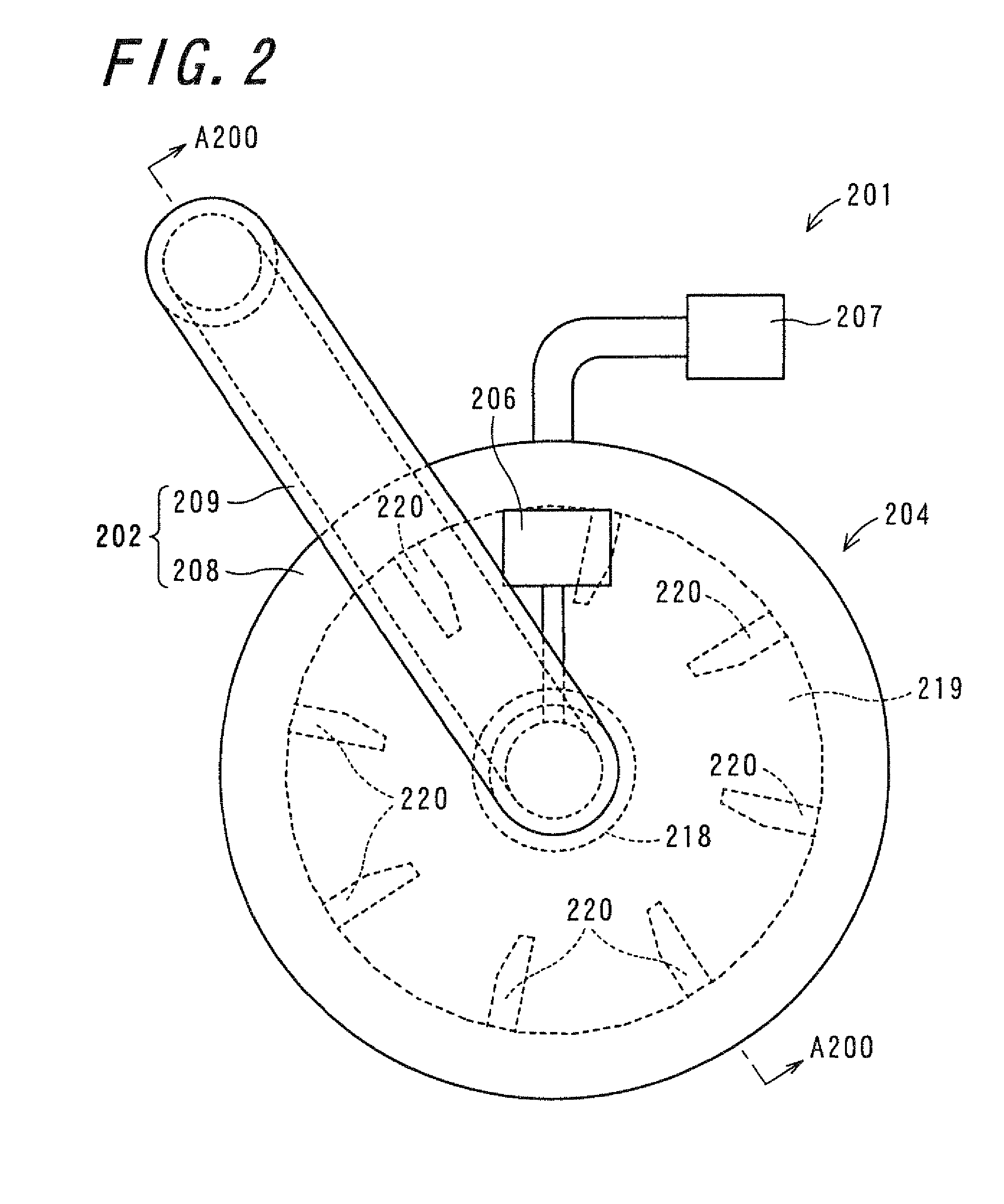
[0203]The pressure outside the powder passage was normal pressure and the resin-layer coated toner of Example 2 was obtained in the same manner as Example 1, except that air pressure from the rotary shaft section was adjusted such that the pressure in the powder passage was 0.04 atm higher than the pressure outside the powder passage.

example 3

[0204]The pressure outside the powder passage was normal pressure and the resin-layer coated toner of Example 3 was obtained in the same manner as Example 1, except that air pressure from the rotary shaft section was adjusted such that the pressure in the powder passage was 0.07 atm higher than the pressure outside the powder passage.


PUM


Abstract

A method for manufacturing a resin-layer coated toner is provided. The method for manufacturing the resin-layer coated toner uses a rotary stirring apparatus including a circulating section, a temperature regulation section, a spraying section and an exhausting section, sprays a liquid substance to particles of toner materials and particles of coating materials in a fluidized state to plasticize such particles from a spraying section by carrier gas and gasifies the liquid, circulates the carrier gas in the powder passage and continuously exhausts the carrier gas including the gasified substance through the exhausting section to the outside of the powder passage, and pressure P1 in the powder passage and pressure P0 outside the powder passage satisfy the following formula (1):0 atm<(Pressure P1 in the powder passage−Pressure P0 outside the powder passage)≦0.3 atm  (1).

Description

CROSS-REFERENCE TO RELATED APPLICATION[0001]This application claims priority to Japanese Patent Application No. 2008-277513, which was filed on Oct. 28, 2008, the contents of which are incorporated herein by reference in its entirety.BACKGROUND OF THE INVENTION[0002]1. Field of the Invention[0003]The present invention relates to a method for manufacturing a resin-layer coated toner and a resin-layer coated toner obtained by the same, a developer including the resin-layer coated toner, as well as a developing apparatus using the developer and an image forming apparatus.[0004]2. Description of the Related Art[0005]Conventionally, a surface modification treatment for coating the surface of powder particles with a coating material has been performed in order to improve characteristics of the powder particles such as toner particles.[0006]As a method for the surface modification treatment of the powder particles such as toner particles, a method is known that a mechanical stirring force ...

Claims


Application Information

Patent Timeline
Patent Type & Authority Patents(United States)
IPC IPC(8): G03G9/08
CPCG03G9/0804G03G9/0825G03G15/08
Inventor KAWASE, YOSHITAKAHARA, TAKASHIAKAZAWA, YOSHIAKI
Owner SHARP KK
Why Eureka
Try Eureka