Joining method for preparing an inverted metamorphic multijunction solar cell
a solar cell, inverted metamorphic technology, applied in the field of joining methods for preparing inverted metamorphic multijunction solar cells, can solve the problems of increasing manufacturing complexity, number of practical difficulties relating to material selection and fabrication steps,
- Summary
- Abstract
- Description
- Claims
- Application Information
AI Technical Summary
Benefits of technology
Problems solved by technology
Method used
Image
Examples
first embodiment
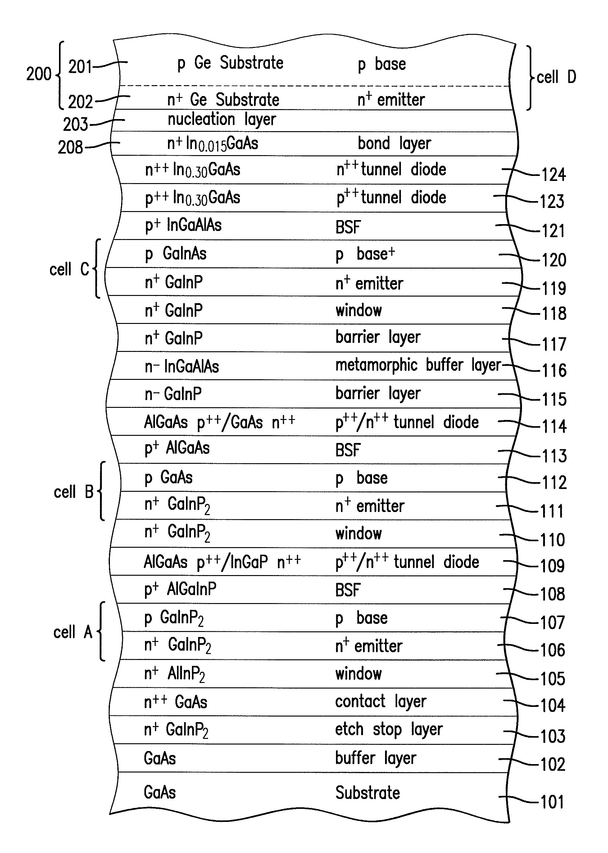
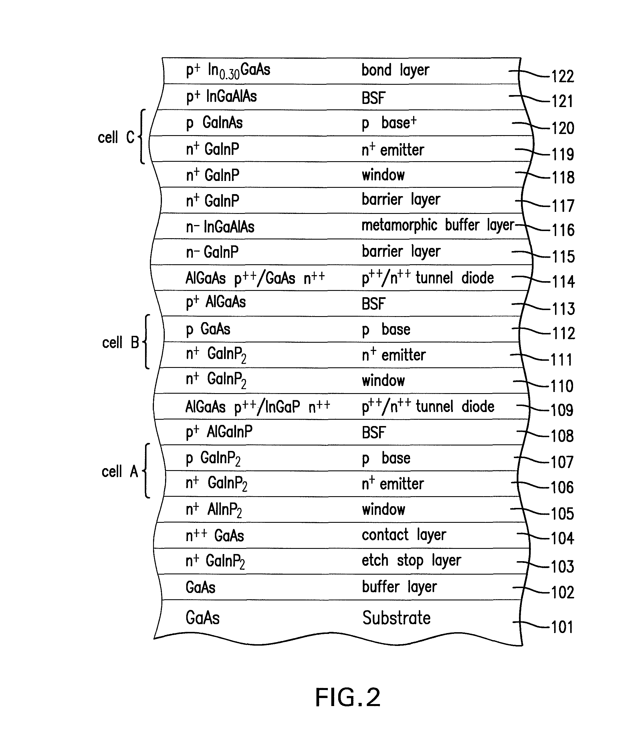
[0107]FIG. 5 is a cross-sectional view of the solar cell of the present invention depicting the semiconductor structure of FIG. 2 bonded with the semiconductor structure of FIG. 4.
[0108]The method of bonding the wafers of the structures of FIG. 2 and FIG. 4 according to the present invention is as follows. The wafers are placed in an ultra high vacuum chamber. The wafers are then exposed to H+ ions at 400° C. to remove all oxides and carbonaceous materials on the bonding surfaces of each wafer. They are then aligned, and are mechanically brought together or compressed to form a bond at near zero pressure. Subsequent processing of the bonded structure will be described below, beginning with the description of FIG. 9.
[0109]Turning to a second embodiment of the present invention, in which the tunnel diode is formed on the second substrate rather than the first substrate, FIG. 6A depicts a cross-sectional view of first a portion of the solar cell in a second embodiment of the present in...
second embodiment
[0116]FIG. 8 is a cross-sectional view of the solar cell of the present invention depicting the substrate of FIG. 6 bonded with the substrate of FIG. 7C.
[0117]FIG. 9 is a highly simplified cross-sectional view of the solar cell semiconductor of FIG. 5 or FIG. 8 depicting just a few of the layers (201, 202, and 203) at the top of the semiconductor structure and of few of the layers (105, 104, 103, 102) at the bottom of the structure over the GaAs substrate 101.
[0118]FIG. 10 is a cross-sectional view of the solar cell of FIG. 9 (i.e., a simplified version of FIG. 5 or FIG. 8) after the next process step in which a metal contact layer 301 is deposited over the exposed surface of the germanium substrate 201. The metal is preferably the sequence of metal layers Ti / Au / Ag / Au, although other metal sequences can be used as well.
[0119]FIG. 11A is a cross-sectional view of the structure of FIG. 10 after the next process step in which an adhesive layer 302 is deposited over the metal layer 301....
PUM
 Abstract
Description
Claims
Application Information
 - R&D
- Intellectual Property
- Life Sciences
- Materials
- Tech Scout
- Unparalleled Data Quality
- Higher Quality Content
- 60% Fewer Hallucinations
Browse by: Latest US Patents, China's latest patents, Technical Efficacy Thesaurus, Application Domain, Technology Topic, Popular Technical Reports.
© 2025 PatSnap. All rights reserved.Legal|Privacy policy|Modern Slavery Act Transparency Statement|Sitemap|About US| Contact US: help@patsnap.com


