Apparatus and method for reducing asymmetric rotor loads in wind turbines during shutdown

a technology of wind turbines and rotors, applied in the direction of rotors, marine propulsion, vessel construction, etc., can solve the problems of extreme loads, the number of fatigue cycles accumulated, and the contribution of extreme loads, and achieve the effect of reducing loads

a technology of wind turbines and rotors, applied in the direction of rotors, marine propulsion, vessel construction, etc., can solve the problems of extreme loads, the number of fatigue cycles accumulated, and the contribution of extreme loads, and achieve the effect of reducing loads

US8240990B2Active Publication Date: 2012-08-14GE INFRASTRUCTURE TECH INT LLC

Image

  • Apparatus and method for reducing asymmetric rotor loads in wind turbines during shutdown
  • Apparatus and method for reducing asymmetric rotor loads in wind turbines during shutdown
  • Apparatus and method for reducing asymmetric rotor loads in wind turbines during shutdown

Examples


Embodiment Construction

[0015]Referring to the drawings wherein identical reference numerals denote the same elements throughout the various views,

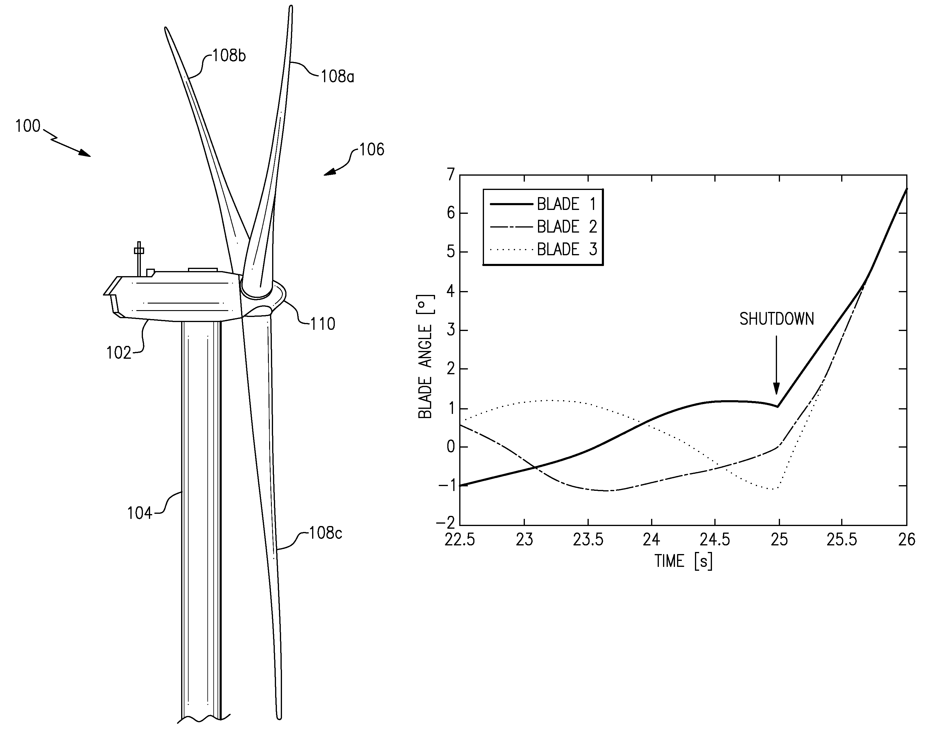
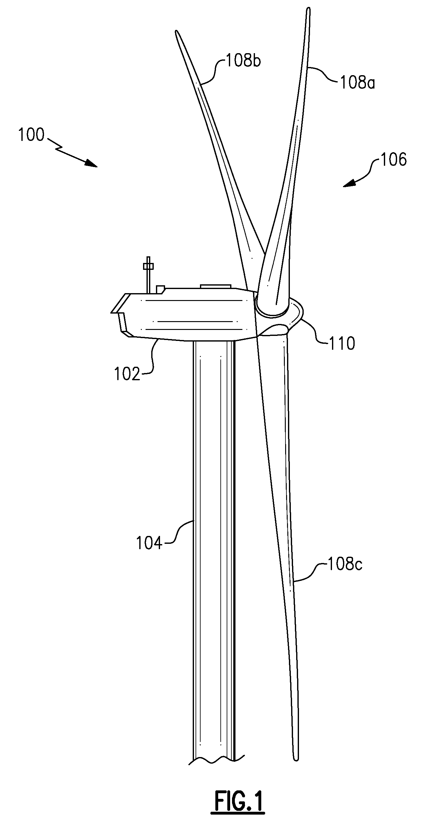
[0016]Referring now to FIG. 1, a wind turbine 100 in some configurations comprises a nacelle 102 housing a generator (not shown in FIG. 1). A nacelle 102 is mounted atop a tall tower 104, only a portion of which is shown in FIG. 1. The wind turbine 100 also comprises a rotor 106 that includes a plurality of rotor blades 108 attached to a rotating hub 110. Although the wind turbine 100 illustrated in FIG. 1 includes three rotor blades 108, there are no specific limits on the number of rotor blades 108 required by the invention.

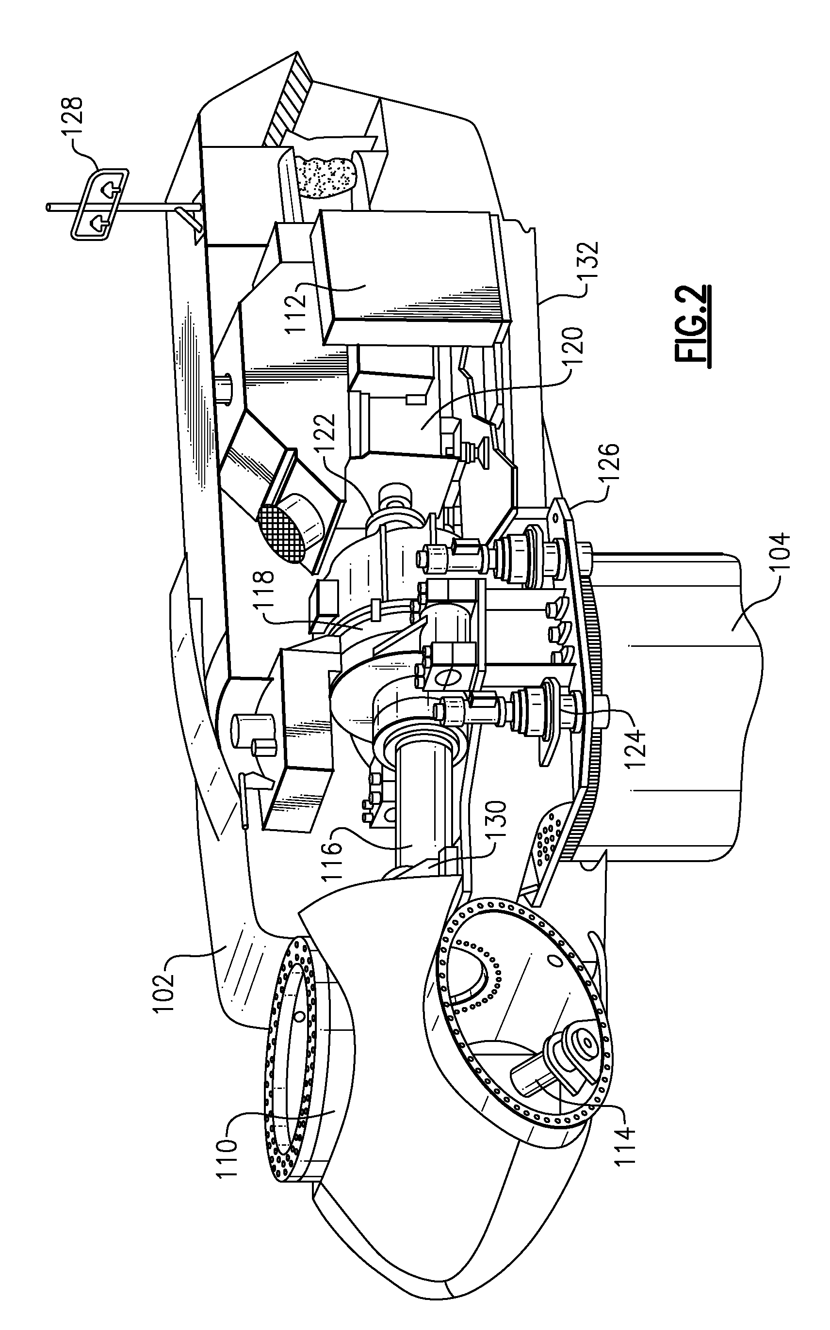
[0017]Referring now to FIG. 2, various components are housed in the nacelle 102 atop the tower 104 of the wind turbine 100. The height of the tower 104 is selected based upon factors and conditions known in the art. In some configurations, one or more microcontrollers within the control panel 112 comprise a control system are used for overa...


PUM


Abstract

An apparatus and method for reducing asymmetric rotor load in a wind turbine includes calculating a time delay for pitching each blade toward feather upon initiation of a shutdown condition. The blades with the larger blade angle begin moving toward feather with an initial pitch rate, while the blade with the smallest blade angle begins moving toward feather with a final pitch rate. Once all the blades have reached approximately an identical blade angle, the blades move simultaneously together to feather at the final pitch rate. By introducing the time delay for pitching the blades having higher blade angles at the final pitch rate, a simple, time-based correction of initial conditions during shutdown reduces the extreme loads on turbine components.

Description

BACKGROUND[0001]This invention relates generally to wind turbines, and more particularly to methods and apparatus for efficiently reducing load in wind turbines.[0002]Recently, wind turbines have received increased attention as an environmentally safe and relatively inexpensive alternative energy source. With this growing interest, considerable efforts have been made to develop wind turbines that are reliable and efficient.[0003]Generally, a wind turbine includes a rotor having multiple blades. The rotor is mounted within a housing or nacelle, which is positioned on top of a truss or tubular tower. Utility grade wind turbines (i.e., wind turbines designed to provide electrical power to a utility grid) can have large rotors (e.g., 80 or more meters in diameter). Blades on these rotors transform wind energy into a rotational torque or force that drives one or more generators, rotationally coupled to the rotor through a gearbox. The gearbox may be used to step up the inherently low rot...

Claims


Application Information

Patent Timeline
14 Aug 2012
Publication
US8240990B2
IPC
F03D7/04; B63H3/00
CPC
F03D7/0224; F03D7/024; F03D7/0264; F03D7/043; F05B2270/328; Y02E10/723; Y02E10/72
Inventors
KAMMER, LEONARDO CESAR; OING, HUBERT