
Casing chuck

Inactive Publication Date: 2012-08-14
VISCASE CORP
View PDF9 Cites 3 Cited by
  • Summary
  • Abstract
  • Description
  • Claims
  • Application Information

AI Technical Summary

Benefits of technology

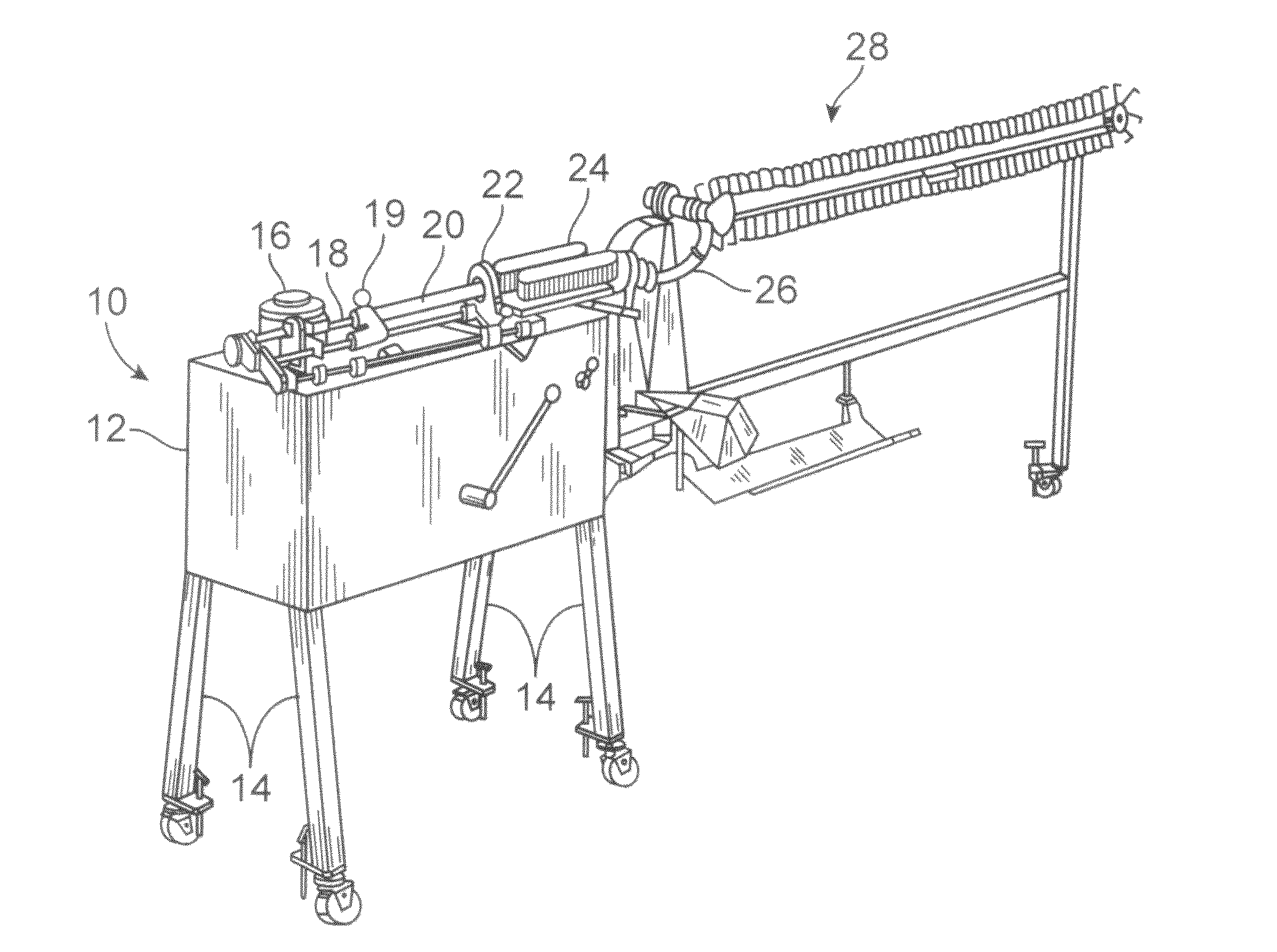
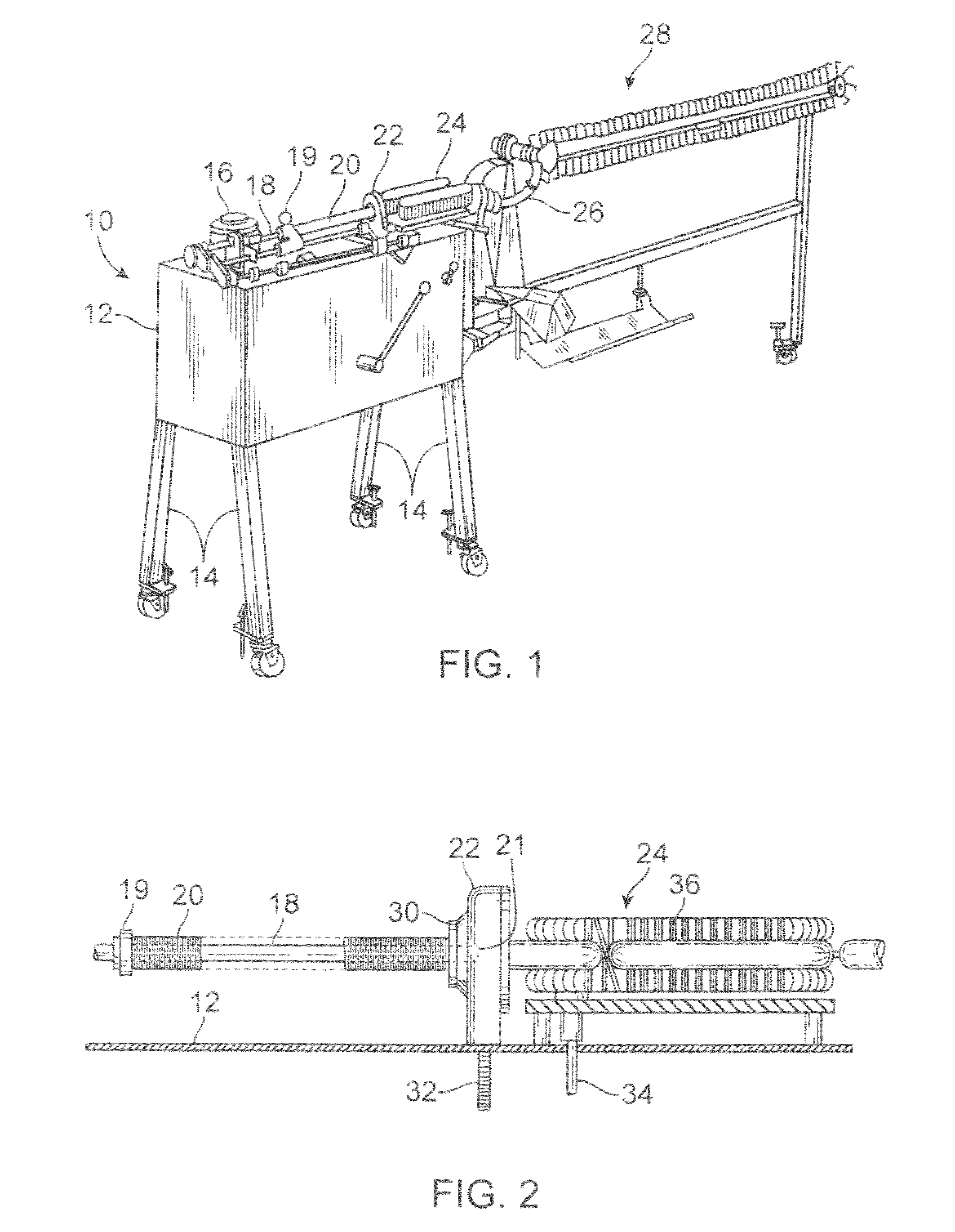
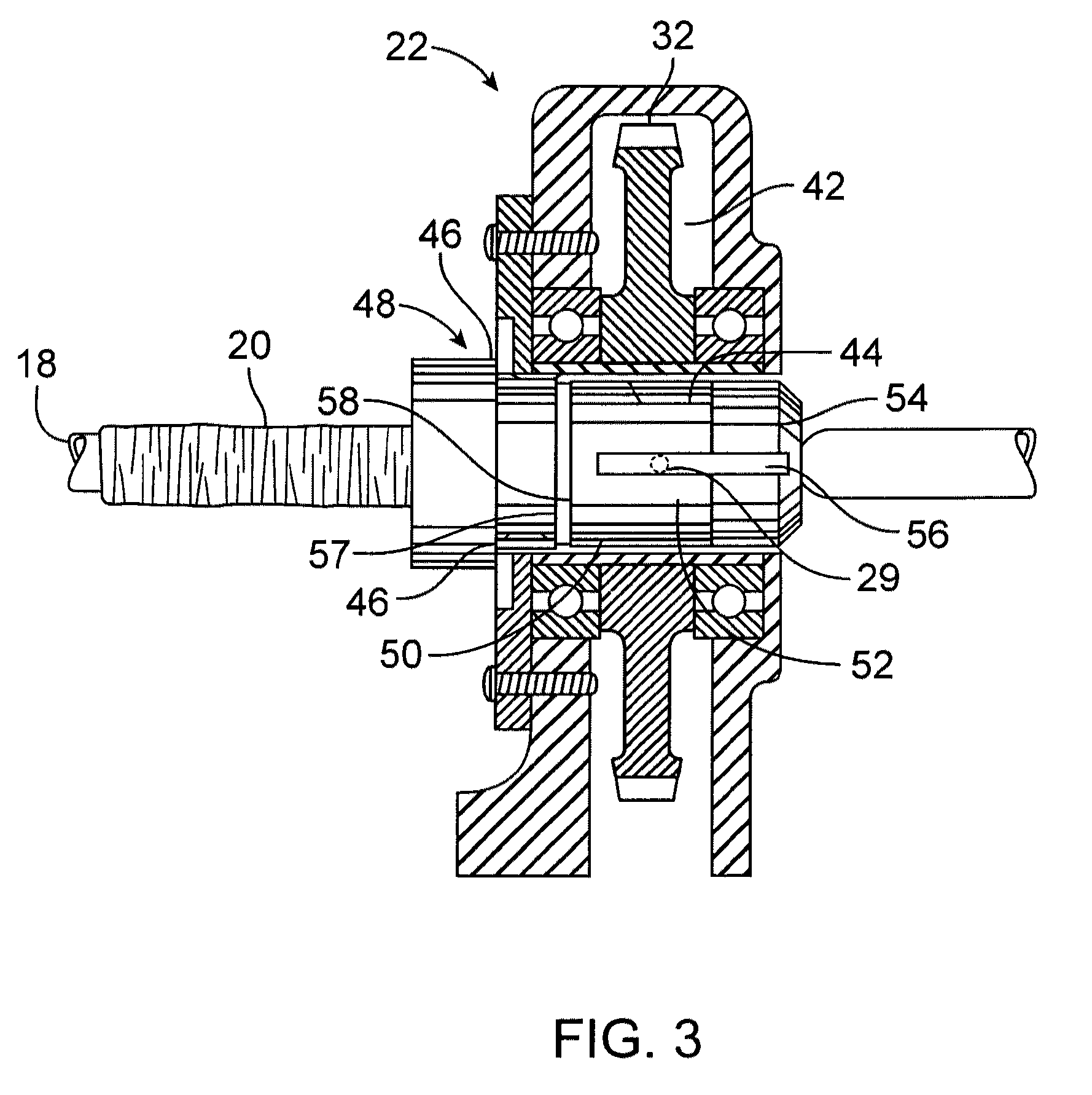
[0014]The present invention is a particular improvement of the chuck member described above, comprising a means for increasing the holdback force on the plastic casing initially situated on the stuffing horn as it is deshirred and moves through the chuck. This is done by providing a means for reducing the inside diameter of the chuck for a portion of the length of the interior hollow bore, thereby decreasing the space available between the outer wall of the stuffing horn and the inner wall of the chuck's bore, and restricting the annular passage for the plastic casing. A preferred means for increasing this holdback force in the inventive chuck is by inserting into a portion of the interior of the chuck an inwardly tapering plastic tubular member that fits snugly against the interior flutes. This plastic tubular member preferably has a smooth interior surface, although it may also have interior flutes. A particularly preferred embodiment is the insertion of an inwardly tapering plastic tubular member that fits snugly against the interior flutes of the chuck, beginning at approximately the intermediate location and continuing forward, for a total distance of from about approximately one-quarter to about one-third of the length of the chuck. This section of the interior hollow bore of the chuck is known as the holdback force increasing zone. The tubular member may have a smooth interior and exterior surface.
[0015]Another embodiment of the present invention for increasing holdback force in the chuck is a one-piece molded chuck with the improvement being the reduction of the inside diameter designed into the chuck's interior hollow bore in the holdback force increasing zone. The reduction of the inside diameter provides the same degree of reduction as is provided by the inserted inwardly tapering plastic tubular member that fits snugly against the interior flutes of the molded chuck, as described above. The improvement to the standard chucks comprises eliminating the multiplicity of longitudinally extending casing engaging flutes in the holdback force increasing zone of the bore of the chuck, and then reducing the inside diameter of the bore in an inwardly tapering manner in the holdback force increasing zone. The interior surface of the holdback force increasing zone is preferably smooth, as in the tubular member insert above.
[0016]However, another embodiment of the present invention allows for retaining the flutes in the holdback force increasing zone but extending their height to provide the same decrease in inside diameter of the bore as does the tubular insert or the one-piece molded chuck.
[0019]Another aspect of this invention relates to a method for controlling the deshirr rate of a plastic casing stick being stuffed with food emulsion including the steps of moving the deshirring and filling casing longitudinally into the casing engaging zone, through the restrictive annular passage of the holdback force increasing zone (the zone between the inside wall of the bore of the inventive chuck and the outside wall of the stuffing horn), thereby increasing the holdback force as the food emulsion is introduced into the casing, and then moving the filled and diametrically restricted casing through a casing deforming zone where the filled casing is gripped by the inventive chuck and rotated about its longitudinal axis.

Problems solved by technology

It has always been a compromise to design a chuck with flutes which provide sufficient gripping for adequate torque transmission without gripping so tightly that there is excessive holdback, as this could result in overstuffing and possible breakage of the casing.
However, it has been discovered that the typical chuck design which works well for cellulosic casings does not provide the same holdback force for plastic casings.
This results in under stuffing of the plastic casing unless other adjustments are made.
Machine adjustments can be made to increase the firmness of the stuffed food product, but there appears to be no reliable adjustment to prevent the initial links of a new shirred stick from being severely understuffed.
This is not necessarily a problem for all stuffing processes, but is a significant problem for machines equipped with automatic loopers because the initial links have inadequate firmness to transfer through typical looper assemblies and frequently jam the equipment in the process, thereby stopping the high-speed production of the food product.
However, this approach has been attempted with limited success to date.

Method used


Image

  • Casing chuck
  • Casing chuck
  • Casing chuck

Examples


example 1

[0051]A series of tests was conducted to compare the longitudinal forces required to pull cellulose and plastic casing through four different chucks (Std. 22, H22-16, H22-18, and H22-19) on a food encasing machine of the FIGS. 1-2 type (Model RT-7 manufactured by Townsend Engineering Company). In this test, nonreinforced shirred cellulosic casing size 25 (dry flat width about 1.32 inches) manufactured by Viskase Companies, Inc. of Darien, Ill., USA, or nylon casing size 22 (dry flat width about 1.36 inches), also manufactured by Viskase Companies, Inc. of Darien, Ill., USA, was used. These casings were manually pulled through the chucks. The drag force or “holdback” force was measured in pounds, and the data are summarized in Table A.

[0052]The chuck labeled as “Std. 22” was a standard plastic molded chuck in commercial use and sold by Townsend Engineering Company for stuffing nonreinforced casing. This commercial chuck is similar to the chuck shown in U.S. Pat. No. RE37,883E, issued...


PUM


Abstract

Chucks for a meat encasing machine that increase the holdback force on plastic casing sticks resulting in fully formed initial links. The invention also includes a method for controlling the deshirr rate of shirred plastic casing sticks inserted in a meat encasing machine to generate fully formed initial sausage links.

Description

CROSS-REFERENCE TO RELATED APPLICATIONS[0001]This application claims the benefit of U.S. Provisional No. 61 / 403,854, filed Sep. 22, 2010, which is incorporated by reference in its entirety.FIELD OF THE INVENTION[0002]The present invention relates to a rotatable chuck for gripping and rotating a plastic casing stick while the casing is being stuffed with a food emulsion, to facilitate the formation of initial links in a standard meat encasing machine. More particularly, the invention relates to rotatable chucks providing an increased friction means which increases drag on the casing. The present invention also relates to a method for using such chucks in a meat encasing machine to control the rate of deshirring of the casing stick, thereby increasing holdback force, or drag, on the plastic casing during deshirring.BACKGROUND OF THE INVENTION[0003]Stuffing or meat encasing machines of the type shown in U.S. Pat. Nos. 3,115,668 and 3,191,222 are commonly used in the manufacture of fran...

Claims


Application Information

Patent Timeline
IPC IPC(8): A22C11/00
CPCA22C11/0263A22C11/10
Inventor OXLEY, JEFFERY A.
Owner VISCASE CORP
Learn More