
Display device using quantum dot

a display device and quantum dot technology, applied in the direction of discharge tube luminescnet screens, identification means, instruments, etc., can solve the problems of reducing the viewing angle of liquid crystal molecules of the display device, not meeting the recent trend of being light and thin, and the cathode ray tube. , to achieve the effect of low cost and simple manufacturing process

Inactive Publication Date: 2012-08-14
LG DISPLAY CO LTD
View PDF2 Cites 30 Cited by
  • Summary
  • Abstract
  • Description
  • Claims
  • Application Information

AI Technical Summary

Benefits of technology

The quantum dot display device maintains a wide viewing angle, achieves high transmittance by eliminating the need for complex light filtering, and simplifies the manufacturing process while reducing costs compared to traditional LCDs.

Problems solved by technology

A cathode ray tube, one of the existing display devices, has a limit so that it may not comply with recent trends of being light and thin.
First, when a voltage is applied to the LCD device, the viewing angle of the liquid crystal molecules of the LCD device is decreased due to the index of refraction anisotropy.
Second, since the LCD is formed in a multilayer structure mainly including a thin film transistor (TFT) array substrate, a color filter substrate, a polarized panel, and a liquid crystal layer, an efficiency of light that passes through the bottom layer to the top layer decreases so that the LCD may have a low transmittance.
Third, since the TFT array substrate or the color filter substrate are formed by depositing and patterning various films, the manufacturing process the LCD device is very complicated.
Fourth, since the LCD device is configured to include various parts such as a backlight unit, liquid crystal, a color filter, and a polarized panel, it cost becomes higher.

Method used


Image

  • Display device using quantum dot
  • Display device using quantum dot
  • Display device using quantum dot

Examples


Embodiment Construction

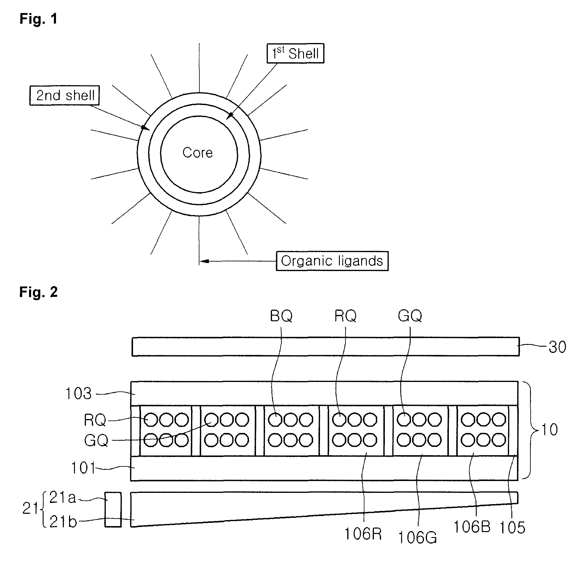
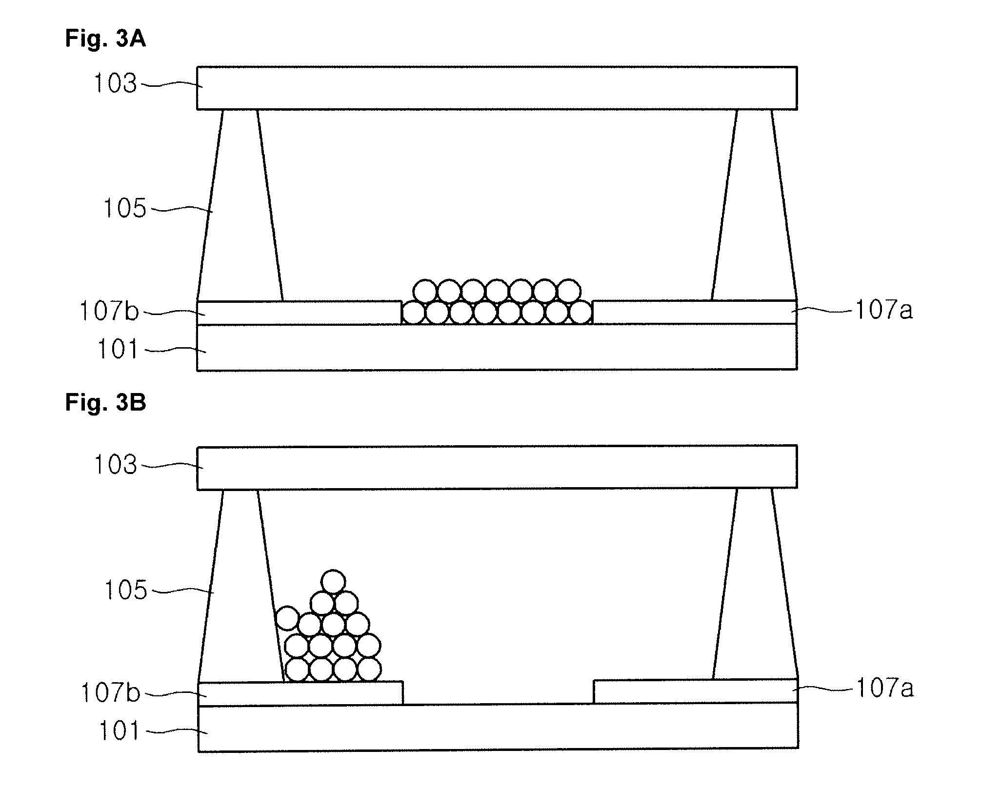
[0031]Reference will now be made in detail to the embodiments of the present disclosure, examples of which are illustrated in the accompanying drawings. These embodiments introduced hereinafter are provided as examples in order to convey their spirits to the ordinary skilled person in the art. Therefore, these embodiments might be embodied in a different shape, so are not limited to these embodiments described here. Also, the size and thickness of the device might be expressed to be exaggerated for the sake of convenience in the drawings. Wherever possible, the same reference numbers will be used throughout this disclosure including the drawings to refer to the same or like parts.

[0032]The present disclosure relates to a display device using quantum dots which are converted to various colors including red, green, and blue colors according to the size and composition thereof. Prior to the description about the structure of the display device of the present disclosure, a quantum dot u...


PUM


Abstract

A display device using quantum dots includes a first substrate and a second substrate disposed to face each other, a partition wall formed between the first and second substrates and defining a unit pixel, a first electrode formed on the first substrate, a second electrode formed to correspond to the first electrode, a backlight unit formed under the first substrate and having a UV light source, a UV blocking film formed above the second substrate, and a red light emitting layer where red quantum dots are formed, a blue light emitting layer where blue quantum dots are formed, and a green light emitting layer where green quantum dots are formed, which are disposed in the unit pixel.

Description

CROSS-REFERENCE TO RELATED APPLICATION[0001]This application claims priority under 35 U.S.C. 119 to Korean Patent Application No. 10-2009-0098830, filed on Oct. 16, 2009, which is hereby incorporated by reference in its entirety.BACKGROUND[0002]1. Field of the Disclosure[0003]This disclosure relates to a display device using quantum dots.[0004]2. Description of the Related Art[0005]Recently, with the rapid development in the field of information and communications, display devices for displaying various information have become more important. A cathode ray tube, one of the existing display devices, has a limit so that it may not comply with recent trends of being light and thin. As such, liquid crystal display (LCD) devices, plasma display panels (PDPs), or electroluminescence display (ELD) devices have been developed as flat panel display devices, and researches and developments thereon are actively carried out.[0006]Among these display devices, the LCD device uses optical anisotro...

Claims


Application Information

Patent Timeline
Patent Type & Authority Patents(United States)
IPC IPC(8): H01L51/00H10K99/00
CPCB82Y20/00C09K11/025C09K11/565C09K11/7492C09K11/75C09K11/883C09K11/892G09F9/30G09F9/372H01J29/20G02B6/0046
Inventor NOH, YOUNG HOON
Owner LG DISPLAY CO LTD
Learn More