Clock integrated circuit
a clock and integrated circuit technology, applied in the direction of generating/distributing signals, pulse techniques, instruments, etc., can solve the problems of consuming a lot of die space, relative complexity of buffer circuits, and increasing costs
- Summary
- Abstract
- Description
- Claims
- Application Information
AI Technical Summary
Benefits of technology
Problems solved by technology
Method used
Image
Examples
Embodiment Construction
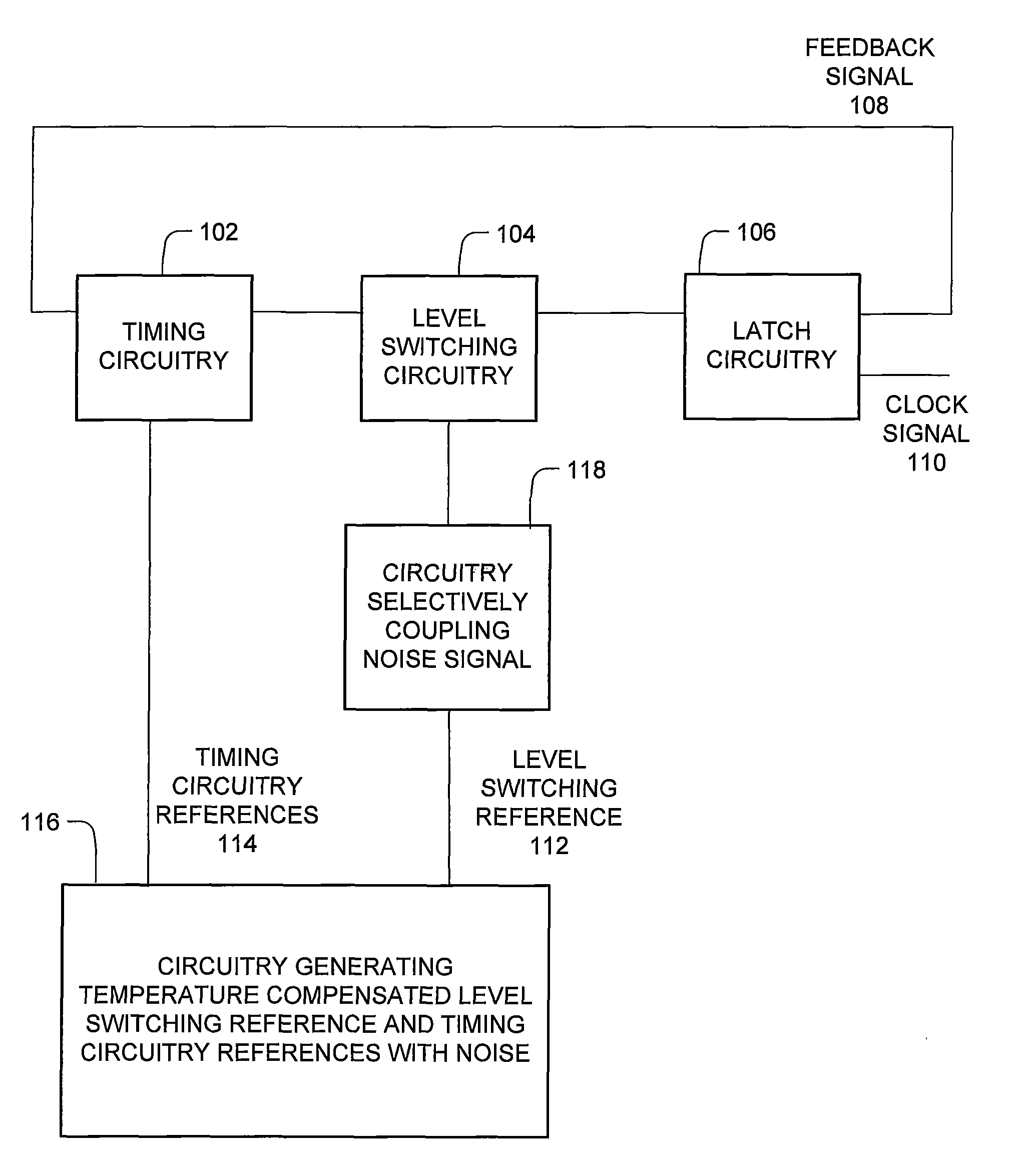
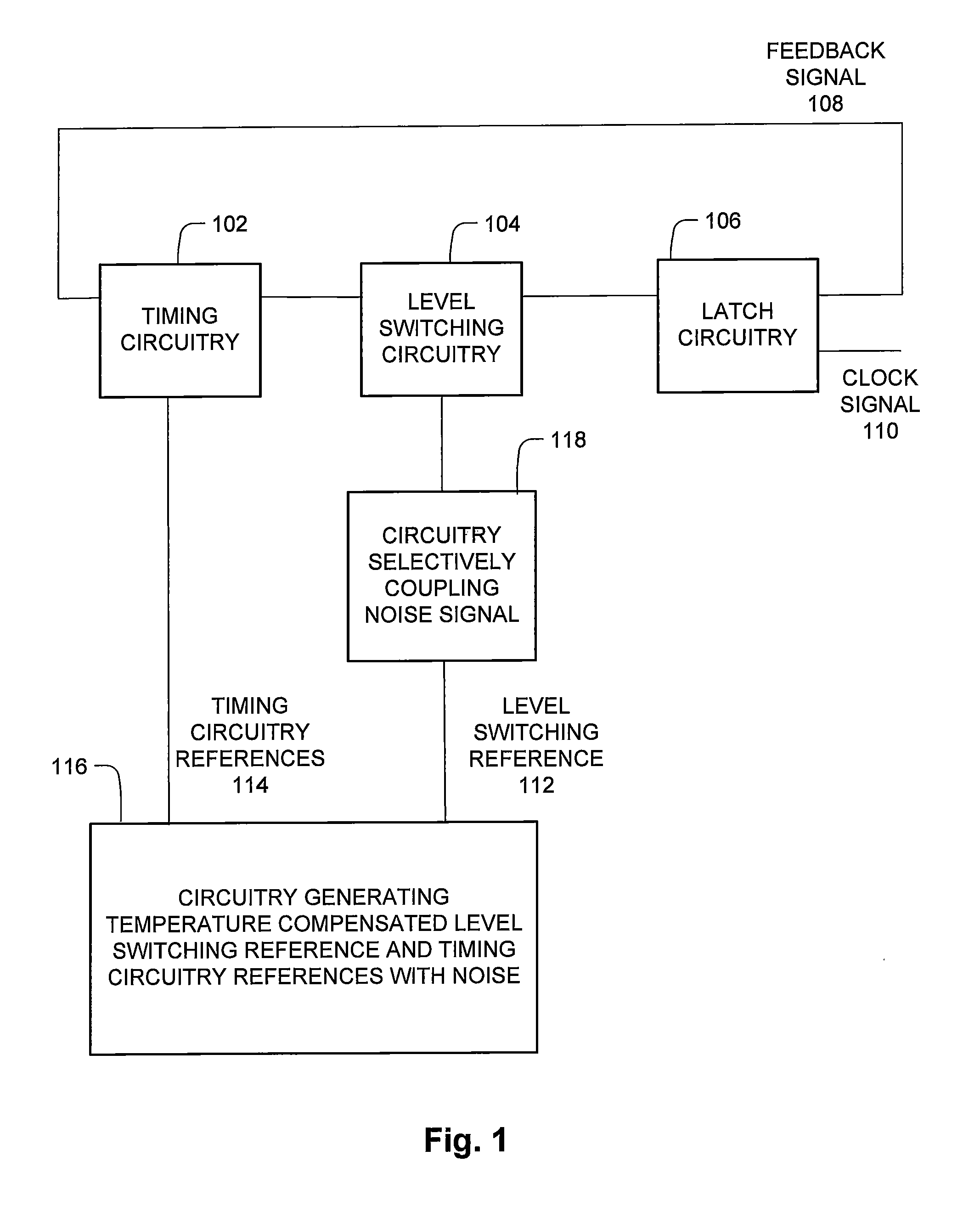
[0078]FIG. 1 is a block diagram of an integrated clock circuit with tolerance to variations such as temperature, ground voltage, and power voltage.
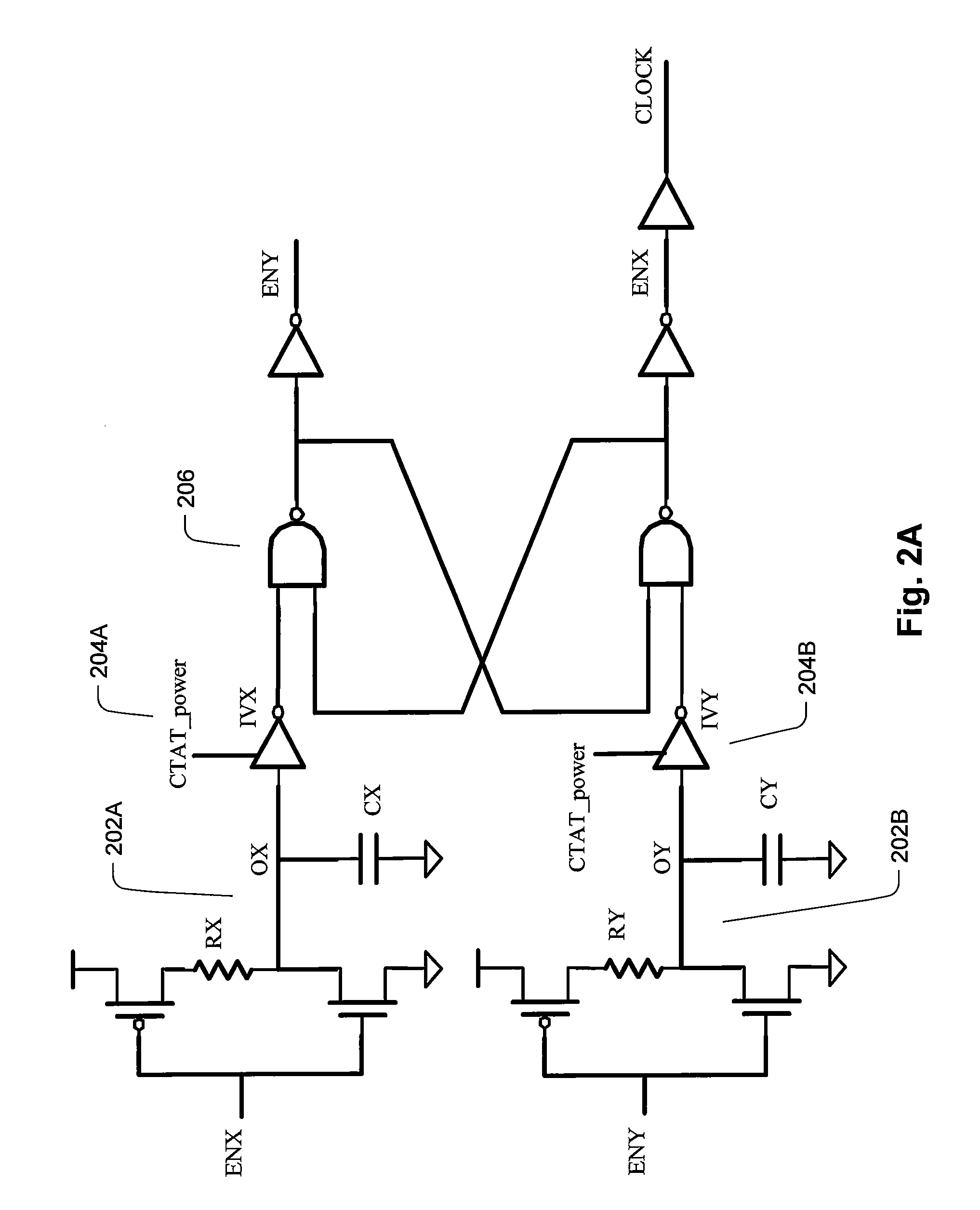
[0079]The clock integrated circuit generally has a loop structure, with timing circuitry 102, level switching circuitry 104, and latch circuitry 106. The latch circuitry 106 generates a feedback signal from latch circuitry 106 back to timing circuitry 102, and the clock signal output 110. The timing circuitry 102 alternates between two reference signals according to a time constant. The time constant accordingly determines the timing of the clock integrated circuit. A typical example of the time constant is an exponential time constant that characterizes the rise and fall of an RC circuit or an RL circuit. The level switching circuitry monitors the output of the timing circuitry 102, and changes the output depending on whether the timing circuitry 102 is sufficiently high, or low. Examples of latch circuitry 106 are an SR latch, SR NAND l...
PUM
 Abstract
Description
Claims
Application Information
 - R&D
- Intellectual Property
- Life Sciences
- Materials
- Tech Scout
- Unparalleled Data Quality
- Higher Quality Content
- 60% Fewer Hallucinations
Browse by: Latest US Patents, China's latest patents, Technical Efficacy Thesaurus, Application Domain, Technology Topic, Popular Technical Reports.
© 2025 PatSnap. All rights reserved.Legal|Privacy policy|Modern Slavery Act Transparency Statement|Sitemap|About US| Contact US: help@patsnap.com


