
Containers used in determining the thermal stability of fuels

a technology of thermal stability and fuel, which is applied in the direction of material heat development, instruments, laboratory glassware, etc., can solve the problems of jet fuel oxidation, poor fuel thermal stability, and deposits that clog fuel nozzles and fuel filters,

Active Publication Date: 2012-08-21
PETROLEUM ANALYZER COMPANY
View PDF21 Cites 1 Cited by
  • Summary
  • Abstract
  • Description
  • Claims
  • Application Information

AI Technical Summary

Benefits of technology

"The present invention provides an apparatus and method for testing the thermal oxidation stability of fluids, particularly aviation fuels. The apparatus includes special purpose containers for measuring the tendency of fuels to form deposits when in contact with heated surfaces. The containers have aeration and venting for testing the thermal oxidation tendency of fuels by testing a sample at an elevated temperature and pressure. The apparatus also includes an aeration device to keep the test sample saturated with dry air during the test. The apparatus can hold a test sample, aerate it, deliver it for testing, and collect the spent sample after the test. The apparatus includes a sample container arm and a waste container arm for easy connection and monitoring of the containers. The sample container arm and the waste container arm ensure that the containers are properly connected and perform the necessary functions during the test. The apparatus also includes a glass frit to allow unimpeded airflow into the test liquid."

Problems solved by technology

When engines were developed for use in jet aircraft, problems began to develop for jet fuel due to poor fuel thermal stability.
At higher temperatures, the jet fuels would oxidize and form deposits that would clog fuel nozzles and fuel filters.
In the past, containers used for (1) the test sample or (2) waste fuel had limitations.
The containers were primarily open vessels that did not provide the operator feedback about being securely positioned, did not contain or capture fuel vapors, and were difficult to secure in place.

Method used


Image

  • Containers used in determining the thermal stability of fuels
  • Containers used in determining the thermal stability of fuels
  • Containers used in determining the thermal stability of fuels

Examples


Embodiment Construction

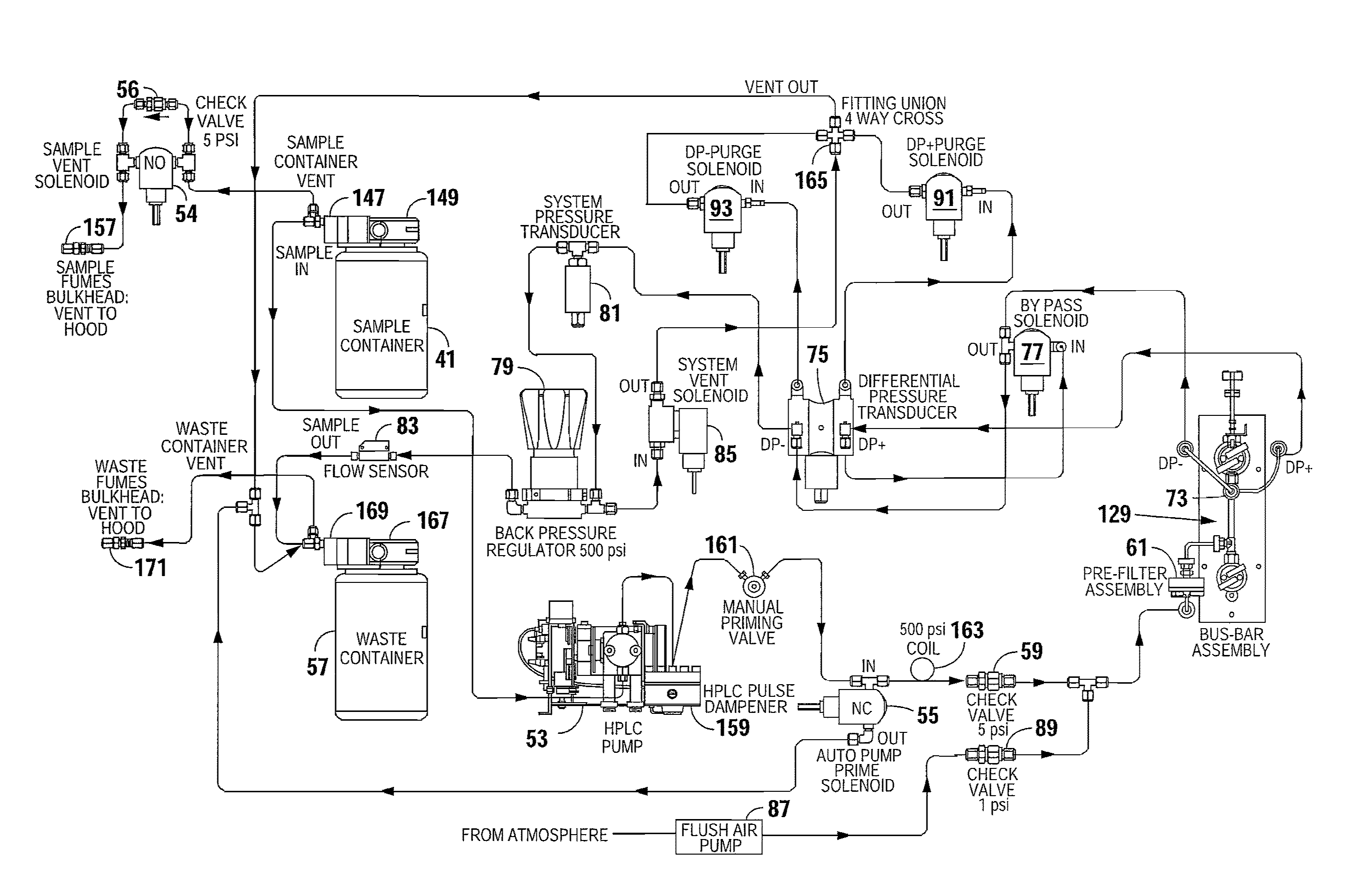
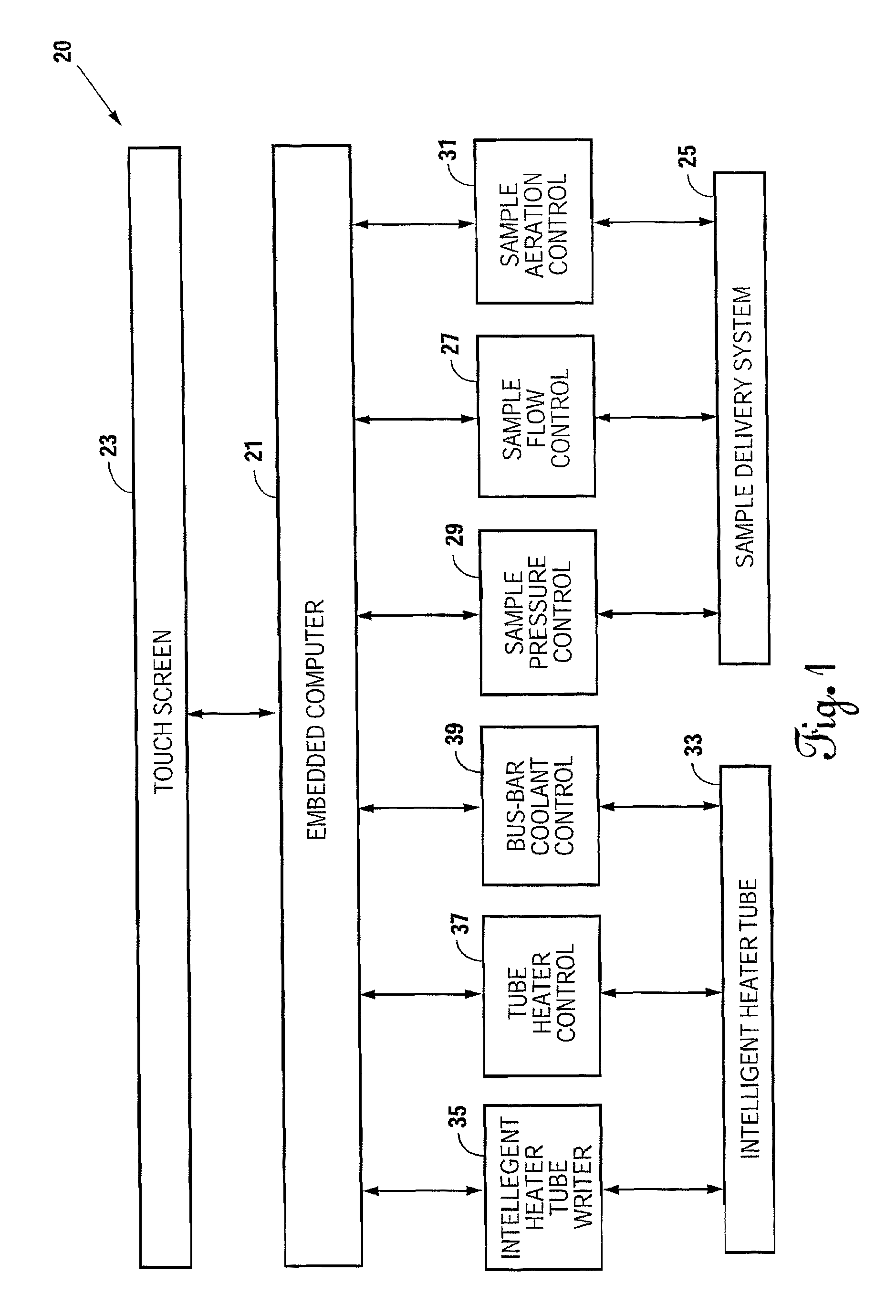
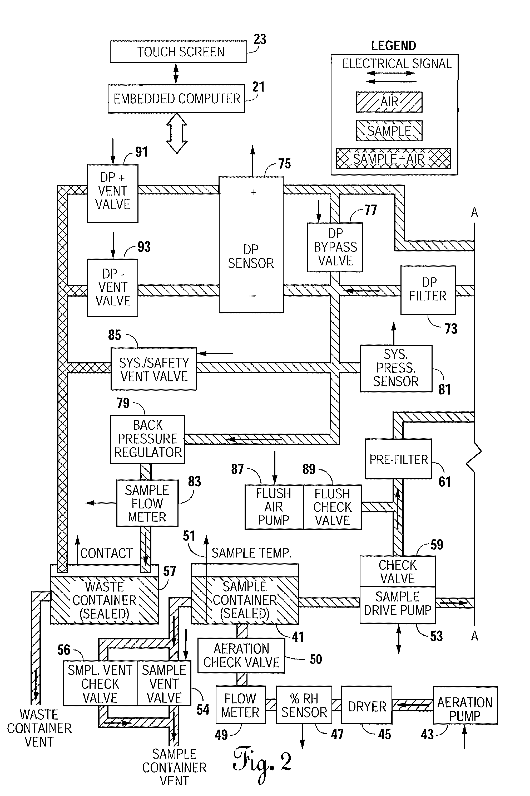
[0042]FIG. 1 is a schematic block diagram of a thermal oxidation stability tester referred to generally by the reference numeral 20. The thermal oxidation stability tester 20 has an embedded computer 21 with a touch screen 23 for user interface. While many different types of programs could be run, in the preferred embodiment, applicant is running C++ in the embedded computer 21. The touch screen 23 displays all of the information from the thermal oxidation stability tester 20 that needs to be conveyed to the user. The user communicates back and forth with the embedded computer 21 through the touch screen 23. If a batch of fuel is to be tested, a test sample is put in the sample delivery system 25.

[0043]It is important to the test to make sure the test sample is oxygen saturated through aeration. Therefore, the embedded computer 21 operates a sample aeration control 31 for a period of time to make sure the sample is fully aerated. The aeration of the sample takes place at the beginni...


PUM

PropertyMeasurementUnit
pressureaaaaaaaaaa
pressureaaaaaaaaaa
sizeaaaaaaaaaa

Abstract

A thermal oxidation tester is shown for determining thermal stability of a fluid, particularly hydrocarbons, when subjected to elevated temperatures. The tendency of the heated fluid to oxidize and (1) form deposits on a surface of a heater tube and (2) form solids therein which are both measured at a given flow rate, temperature and time. The measured results are used to determine whether a fluid sample passes or fails the test. Specifically constructed containers used in a thermal oxidation tester are shown. These containers (1) reduce physical contact to hydrocarbon test fuels, (2) reduce exposure to hydrocarbon fuel vapors, (3) reduce environmental impact by reducing chemical spills, and (4) improve overall work flow of test.

Description

CROSS REFERENCE TO RELATED APPLICATIONS[0001]This is a continuation-in-part of U.S. patent application Ser. No. 12 / 838,104, filed on Jul. 16, 2010, having at least one overlapping inventor and the same assignee.BACKGROUND OF THE INVENTION[0002]1. Technical Field[0003]This invention relates to methods and devices for measuring the thermal characteristics of fuels. Specifically, this invention relates to containers used in measuring the thermal oxidation tendencies of fuels for liquid hydrocarbon-burning engines.[0004]2. Background Art[0005]When engines were developed for use in jet aircraft, problems began to develop for jet fuel due to poor fuel thermal stability. At higher temperatures, the jet fuels would oxidize and form deposits that would clog fuel nozzles and fuel filters. These deposits would also collect in the jet engine.[0006]While various tests were devised and used in the 1950s and 60s to rate the thermal oxidation characteristics of jet fuels prior to being used in jet ...

Claims


Application Information

Patent Timeline
Patent Type & Authority Patents(United States)
IPC IPC(8): G01N33/22G01N1/10G01N25/00
CPCG01N33/2805
Inventor YOUNGBLOOD, LARRY M.ANDERSON, DAVID G.YANG, GUOXINGBERKHOUS, SCOTT K.SPINO, LARRY A.
Owner PETROLEUM ANALYZER COMPANY
Learn More