[0030]Referring initially to FIG. 3, there is illustrated an end elevation view of a prior art AC induction motor, generally designated as 500. Motor 500 has a motor frame 502, a stator 504, a rotor 506 having a shaft 508, an air gap 505 between stator 504 and rotor 506, a bearing mount 510, and a bearing 512 having an outer race 514 and an inner race 516. In the shown embodiment, bearing 512 is either a ball bearing or roller bearing. Stator 504 is rigidly connected to frame 502. Rotor 506 is maintained in place by bearing 512. Outside race 514 of bearing 512 is rigidly connected to bearing mount 510, and inner race 516 of bearing 512 is rigidly connected to rotor shaft 508. In the figure, the broken circle represents the path of rotation of inner race 516 with respect to outer race 514 of bearing 512. Because of air gap 505, rotor 506, inner race 516, and rotor shaft 508 are free to rotate with respect to fixed motor frame 502, stator 504, bearing mount 510, and outer race 514. In the figure arrows show which elements freely rotate.
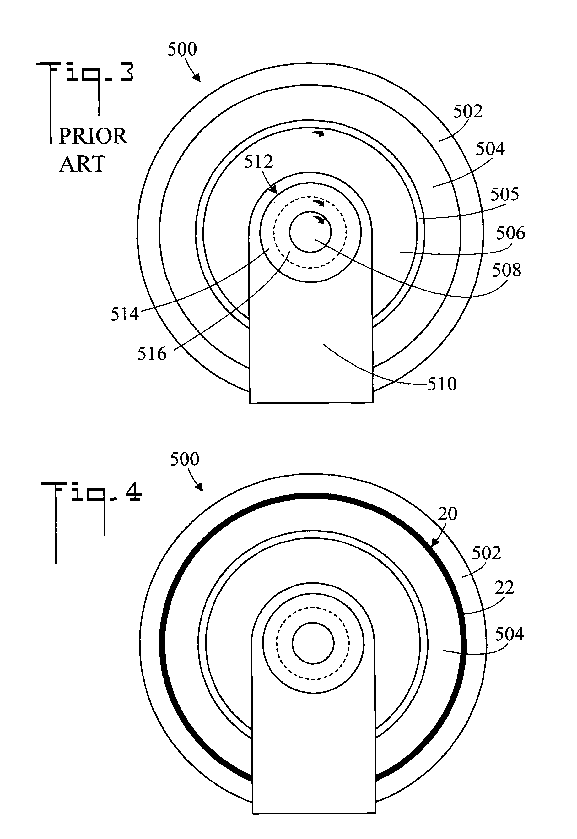
[0031]Referring now to FIG. 4, there is shown an end elevation view of an AC induction motor 500 which includes a first embodiment of a method and apparatus for mitigating bearing failure in the motor, generally designated as 20. To prevent high frequency vibrations from exciting bearing 512 and causing cavitation, a resilient vibration-absorbing material 22 in the form of a dampening spacer is circumferentially inserted between motor frame 502 and stator 504. In an embodiment, the hardness of vibration-absorbing material 22 can vary between a Shore A hardness of about 30 and about 60, as is obtainable using for example a Dow Corning® silicone rubber RTV 3110.
[0032]The reference to a specific silicone material and Shore A harnesses are to be seen as examples only. Many other materials known to the industry are suitable to be used in the design of attenuators for high frequency vibrations. Additionally, the vibration-absorbing spacers 22 can consist of physically separated vibration-absorbing spacers 22 rather than a continuous spacer installed around stator 504 (refer to FIG. 7). Actual physical shaft displacement data at 20 kHz was measured in a laboratory environment to be approximately 7 mm E-06. This value represents a very small displacement. Because the actual physical displacement of the motor shaft is very small in amplitude, the rigidity and thickness of high frequency vibration-absorbing material 22 can be chosen to limit the physical displacement of the stator 504 from being excessively large under the influence of the magnetic field, thus preventing it from appreciably reducing the air gap 505 between the stator 504 and rotor 506 from becoming too small or nonexistent (i.e. a sufficient air gap 505 is always maintained). In other words, the shape and thickness of vibration-absorbing material 22 is such that it prevents stator 504 from directly contacting motor rotor 506. Put another ways, vibration-absorbing material 22 is chosen so that it limits the relative motion of stator 504 and rotor 506 so that air gap 505 is always maintained. In an embodiment, a 1/16 inch thickness has been found useful.
[0033]FIG. 5 is an end elevation view of an AC induction motor 500 which includes a second embodiment of the method and apparatus for mitigating bearing failure in the motor. In this embodiment vibration-absorbing material 22 is placed between bearing mount 510 and outer race 514 of bearing 512.
[0034]FIG. 6 is an end elevation view of an AC induction motor 500 which includes a third embodiment of the method and apparatus for mitigating bearing failure in the motor. In this embodiment vibration-absorbing material 22 is placed between inner race 516 of bearing 512 and shaft 508 of rotor 506.
[0035]FIG. 7 is an end elevation view showing another placement of vibration-absorbing material 22. In this embodiment vibration-absorbing spacers 22 consist of a plurality of physically separated vibration-absorbing spacers 22 rather than the continuous spacers shown in FIGS. 4-6.
[0036]In summary, a method for mitigating bearing failure in an AC induction motor 500 having a motor frame 502, a stator 504, a rotor 506 having a shaft 508, an air gap 505 between stator 504 and rotor 506, a bearing mount 510, and a bearing 512 having an outer race 514 and an inner race 516, includes:
[0037]placing a vibration-absorbing material 22 in at least one of the following locations; [0038] (1) between motor frame 502 and stator 504; [0039] (2) between bearing mount 510 and outer race 514; and, [0040] (3) between inner race 516 and shaft 508.
[0041]The method further including:
[0042]placing vibration-absorbing material 22 between motor frame 502 and stator 504.
[0043]The method further including:
[0044]placing vibration-absorbing material 22 between bearing mount 510 and outer race 514.
[0045]The method further including:
[0046]placing vibration-absorbing material 22 between inner race 516 and shaft 508.
[0047]The method further including:
[0048]vibration-absorbing material 22 being a silicone rubber.
[0049]The method further including:
[0050]vibration-absorbing material 22 having a Shore A hardness of between about 30 and about 60.
[0051]The method further including:
[0052]vibration-absorbing material 22 limiting relative motion of stator 504 and rotor 506 so air gap 505 is always maintained.
[0053]The embodiments of the method and apparatus described herein are exemplary and numerous modifications, combinations, variations, and rearrangements can be readily envisioned to achieve an equivalent result, all of which are intended to be embraced within the scope of the appended claims. Further, nothing in the above-provided discussions of the method and apparatus should be construed as limiting the invention to a particular embodiment or combination of embodiments. The scope of the invention is best defined by the appended claims.