Method for manufacturing thermally-assisted magnetic recording head comprising light source unit and slider

a technology of magnetic recording head and light source unit, which is applied in the field of thermally assisted magnetic recording head, can solve the problems of deterioration in the thermal stability of the magnetization, the head cannot write data to the magnetic recording medium, and the problem of more significant problems to be solved, so as to achieve good joining and melt more efficiently

Active Publication Date: 2012-08-21
TDK CORPARATION +1
View PDF12 Cites 29 Cited by
  • Summary
  • Abstract
  • Description
  • Claims
  • Application Information

AI Technical Summary

Benefits of technology

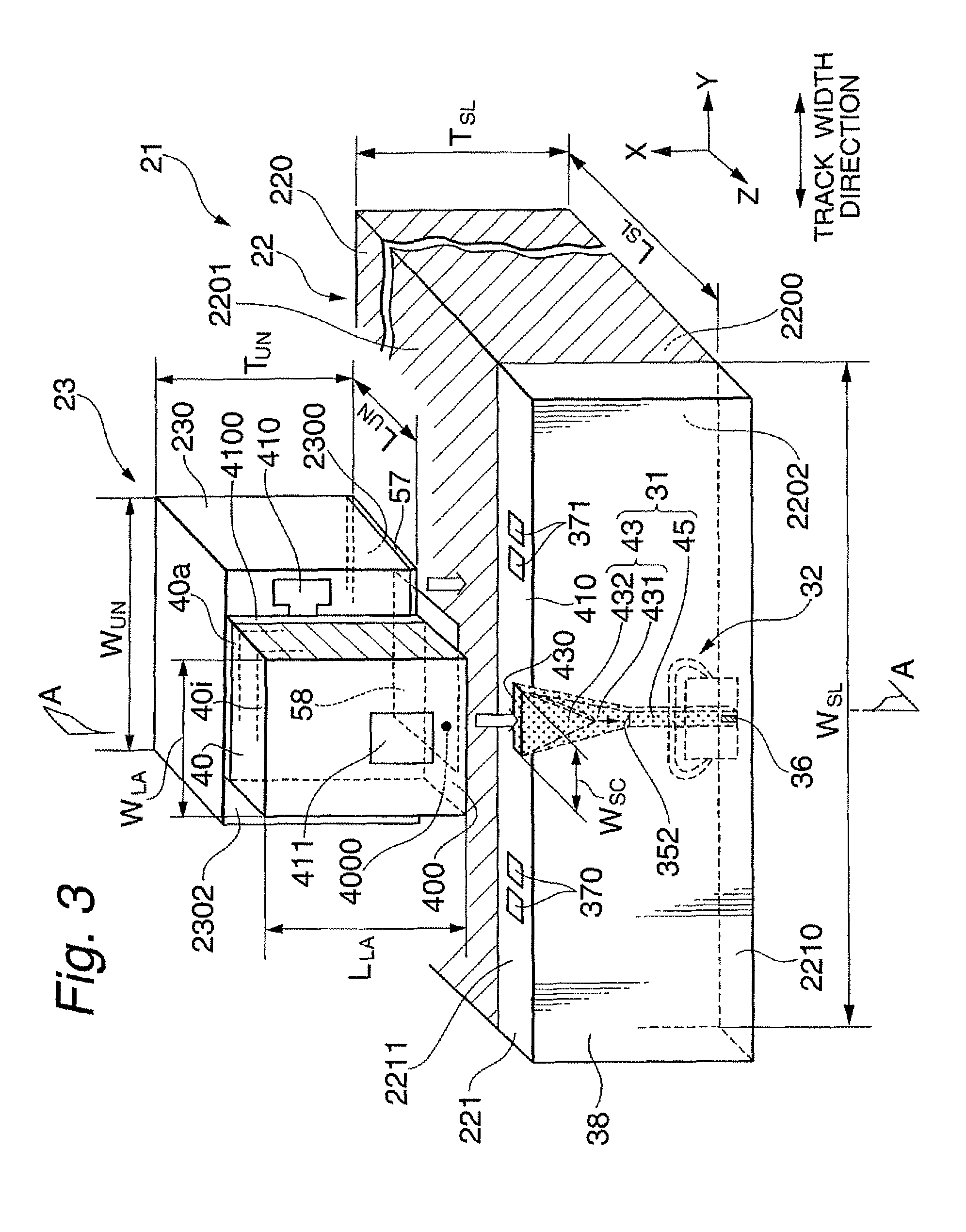
[0024]In the above-described manufacturing method of the thermally-assisted magnetic recording head, since the unit adhesion material layer can be melted by the light that includes a predetermined wavelength and has been transmitted through the unit substrate in bonding of the light source unit and the slider, high alignment accuracy can be achieved while joining with higher bonding strength and less change with time can be achieved. Further, the use of the unit adhesion material layer made of Sn, Sn alloy, Pb alloy or Bi alloy enables joining that does not adversely affect the joining between the unit substrate and the light source by a light-source adhesion material layer (solder layer).
[0026]Furthermore, in the manufacturing method according to the present invention, it is preferable that the light source is activated, and the light source unit and the slider are aligned in such a way that the light generated from the light source enters the optical system. This alignment method is a so-called active alignment method, which can achieve high alignment accuracy. Furthermore, it is also preferable that the melting of the unit adhesion material layer by the entering of the light including the predetermined wavelength is assisted by heating the unit adhesion material layer to a high temperature with a heat generated from the activated light source.
[0028]Further, in the manufacturing method according to the present invention, it is preferable that the slider comprises a magnetic head element configured to write and / or read data, and the slider substrate is made of a material having a lower thermal conductivity than a material of the unit substrate so that conduction of a heat generated by the entering of the light including the predetermined wavelength to the magnetic head element is limited. By controlling the thermal conductivity of the slider substrate, irradiating the unit adhesion material layer with the light that includes the predetermined wavelength and has passed through the unit substrate and melting the layer, adverse influence of heat generated by the irradiation on the magnetic head element provided in the slider can be avoided. Further, it is also preferable that, during the alignment, a holding means to hold the light source unit is used as a heatsink for the heat generated by the entering of the light including the predetermined wavelength.
[0030]Furthermore, in the manufacturing method according to the present invention, it is preferable that, as the light including the predetermined wavelength, a circularly- or elliptically-polarized light is preferably used, and a P-polarized light is also preferably used. By using such light, the light that includes the predetermined wavelength and has entered the unit substrate can be more absorbed into the unit substrate. As a result, the unit adhesion material layer can be melted more efficiently, thereby achieving good joining.

Problems solved by technology

However, the decrease in size of the magnetic grains raises a problem of degradation in thermal stability of the magnetization due to the decrease in volume.
As a result, the head cannot write data to the magnetic recording medium when the anisotropic magnetic field of the medium exceeds the write field limit.
However, from the beginning, more significant problem to be solved exists in where and how a light source with a sufficiently high output of light should be disposed inside a head.
Therefore, it is an important issue to properly align and bond a light source unit and a slider in manufacturing of a head having the “composite slide structure”.
However, in the conventional soldering methods, the light source unit and the slider are heated in a heating unit in the process of melting solder, and are therefore exposed to a considerably high temperature for certain duration of time.
When these magnetic head elements are heated to a high temperature higher than 200° C., for example, the magnetic pole tends to thermally expand to protrude to an undesirable extent or an MR multilayer structure tends to degrade, which can result in defects.

Method used


Image

  • Method for manufacturing thermally-assisted magnetic recording head comprising light source unit and slider
  • Method for manufacturing thermally-assisted magnetic recording head comprising light source unit and slider
  • Method for manufacturing thermally-assisted magnetic recording head comprising light source unit and slider

Examples


Embodiment Construction

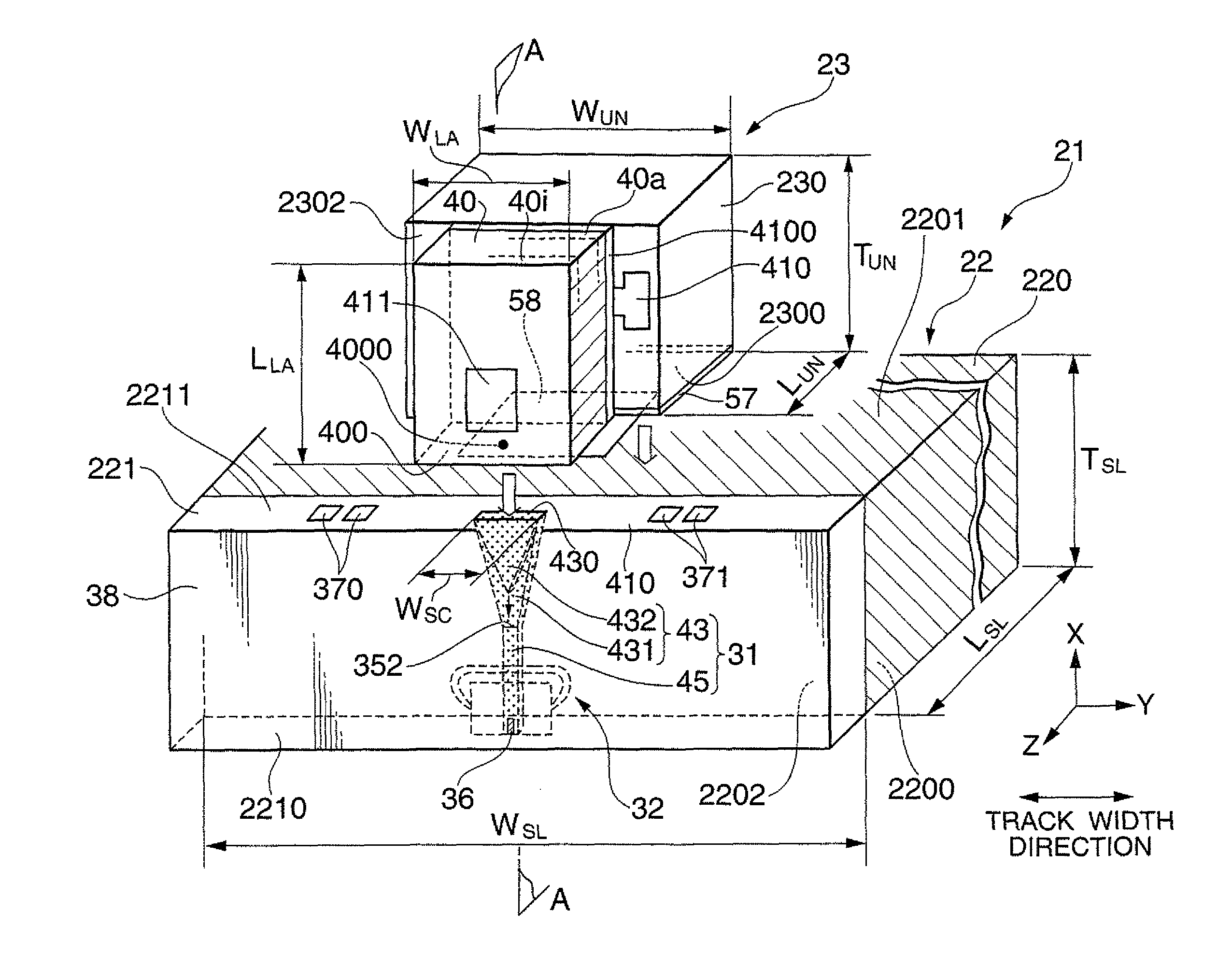
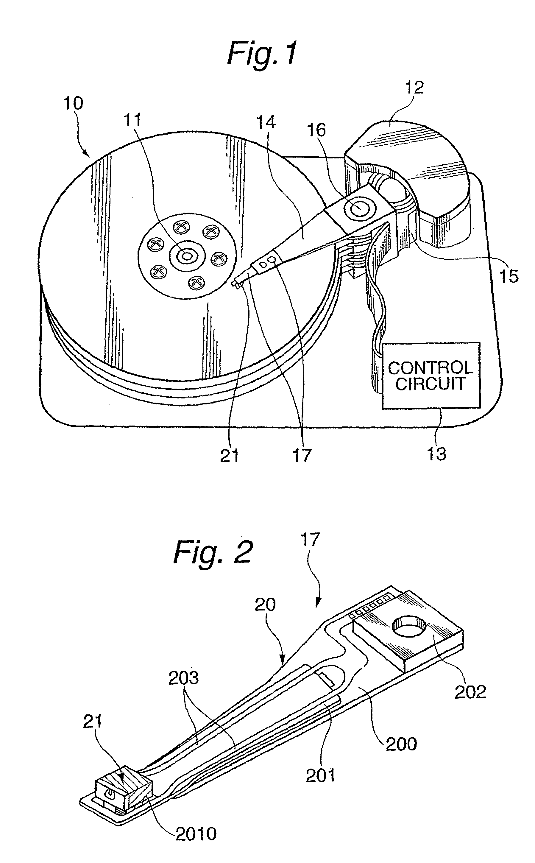
[0046]FIG. 1 shows a perspective view schematically illustrating a structure of a major part in one embodiment of a magnetic disk apparatus according to the present invention. FIG. 2 shows a perspective view schematically illustrating a structure of a major part in one embodiment of a head gimbal assembly (HGA) according to the present invention. In FIG. 2, the side of the HGA opposed to the surface of a magnetic disk is presented as the upper side.

[0047]A magnetic disk apparatus as a magnetic recording apparatus shown in FIG. 1 includes: a plurality of magnetic disks 10 rotating around a rotational axis of a spindle motor 11; an assembly carriage device 12 provided with a plurality of drive arms 14 thereon; an HGA 17 attached on the top end portion of each drive arm 14 and provided with a thermally-assisted magnetic recording head 21; and a recording / reproducing and light-emission control circuit 13 for controlling write / read operations of the thermally-assisted magnetic recording ...


PUM

PropertyMeasurementUnit
melting pointaaaaaaaaaa
temperatureaaaaaaaaaa
transmittanceaaaaaaaaaa

Abstract

A method for manufacturing a thermally-assisted magnetic recording head is provided, in which a light source unit including a light source and a slider including an optical system are bonded. A unit substrate is made of a material transmitting light having a predetermined wavelength, and a unit adhesion material layer that contains Sn, Sn alloy, Pb alloy or Bi alloy is formed on the light source unit and / or the slider. The manufacturing method includes: aligning the light source unit and the slider in such a way that a light from the light source can enter the optical system and the unit adhesion material layer is sandwiched therebetween; and causing a light including the predetermined wavelength to enter the unit substrate to melt the unit adhesion material layer. The unit adhesion material layer melted by the light including the predetermined wavelength can ensure high alignment accuracy as well as higher bonding strength and less change with time.

Description

CROSS-REFERENCE TO RELATED APPLICATION[0001]This application is a continuation-in-part application of U.S. application Ser. No. 12 / 726,981, filed on Mar. 18, 2010, now pending.BACKGROUND OF THE INVENTION[0002]1. Field of the Invention[0003]The present invention relates to a thermally-assisted magnetic recording head constituted by joining a light source unit including a light source that emits light for performing thermally-assisted magnetic recording and a slider, and relates to a method for manufacturing the thermally-assisted magnetic recording head.[0004]2. Description of the Related Art[0005]As the recording densities of magnetic recording apparatuses become higher, as represented by magnetic disk apparatuses, further improvement has been required in the performance of thin-film magnetic heads and magnetic recording media. The magnetic recording medium is generally a kind of discontinuous body of magnetic grains gathered together, and each of the magnetic grains has an almost s...

Claims


Application Information

Patent Timeline
Patent Type & Authority Patents(United States)
IPC IPC(8): G11B11/00
CPCG11B5/314G11B5/6088G11B2005/001G11B2005/0021
Inventor SHIMAZAWA, KOJITSUCHIYA, YOSHIHIROTAKAYAMA, SEIICHIMORI, NOBUYUKIITO, YASUHIROTANAKA, KOSUKESHINDO, OSAMUFUJII, RYUJIHONDA, TAKASHISASAKI, YOSHITAKA
Owner TDK CORPARATION
Why Eureka
Try Eureka