Image decoding device, image decoding method, and image decoding program

a decoding device and image technology, applied in the field of image decoding apparatus, image decoding method and image decoding program, can solve the problems of wasteful calculation, large amount of calculation, poor efficiency, etc., and achieve high speed decoding processing

Inactive Publication Date: 2012-08-21
SONY CORP
View PDF7 Cites 109 Cited by
  • Summary
  • Abstract
  • Description
  • Claims
  • Application Information

AI Technical Summary

Benefits of technology

[0022]An object of the present invention is to provide a novel image decoding apparatus, a novel image decoding method and a novel image decoding program which can eliminate or solve problems that prior arts as described above have.
[0023]Another object of the present invention is to provide an image decoding apparatus, an image decoding method and an image decoding program which are adapted for performing realization of improvement in efficiency of inverse-transform processing by inverse-transform means and reduction in calculation cost to have ability to attain realization of high speed decoding processing.
[0030]In the image decoding apparatus according to the present invention, when inverse quantization means inverse-quantizes transform coefficients which have been decoded by the decoding means, existence of each transform coefficient is indicated as a flag every processing block of inverse quantization, and the inverse transform element serves to change inverse transform processing to be implemented to inverse quantization transform coefficients within processing block by using the flag which has been indicated by the inverse quantization means. Accordingly, it becomes unnecessary to perform matrix calculations in length and breadth directions at all blocks. Thus, high speed decoding processing can be realized.
[0031]In the image decoding method according to the present invention, since existence of each transform coefficient is indicated as a flag every processing block of inverse quantization when inverse-quantization step serves to inverse-quantize transform coefficients which have been decoded by the decoding step, and the inverse transform step serves to change inverse transform processing to be implemented to inverse quantization transform coefficients within processing block by using the flag which has been indicated by the inverse quantization step, it becomes unnecessary to perform matrix calculations in length and breadth directions at all blocks. Thus, high speed decoding processing can be made.
[0032]In the image decoding program according to the present invention, since when the inverse quantization step serves to inverse-quantize transform coefficients which have been decoded by the decoding step, existence of each transform coefficient is indicated as a flag every processing block of inverse-quantization, and the inverse transform step serves to change inverse transform processing to be implemented to inverse quantization transform coefficients within processing block by using the flag which has been indicated by the inverse quantization step, it becomes unnecessary to perform matrix calculations in length and breadth directions at all blocks. Thus, high speed decoding processing can be realized.

Problems solved by technology

However, at the decoding processing, in order to perform inverse-transform processing of all blocks in which an image is divided into 8×8 / 4×4 pixels, calculation quantity would become vast (large).
Since there is no change of value also after matrix processing (transformed values are all zero) with respect to block in which any coefficient does not exist (pixel values are all zero), wasteful calculation would be performed.
In addition, also in the case where only DC component of block exists, or deviation of coefficients exists within block, there are instances where efficiency is not good for the purpose of performing two times of matrix calculations of 8×8 / 4×4.

Method used


Image

  • Image decoding device, image decoding method, and image decoding program
  • Image decoding device, image decoding method, and image decoding program
  • Image decoding device, image decoding method, and image decoding program

Examples


second embodiment

[0058]Accordingly, also in the second embodiment, it becomes unnecessary to perform matrix calculations in length and breadth directions at all blocks consisting of 4×4 pixels, 8×8 pixels or 16×16 pixels. Thus, at the image decoding apparatus, high speed decoding processing can be realized.

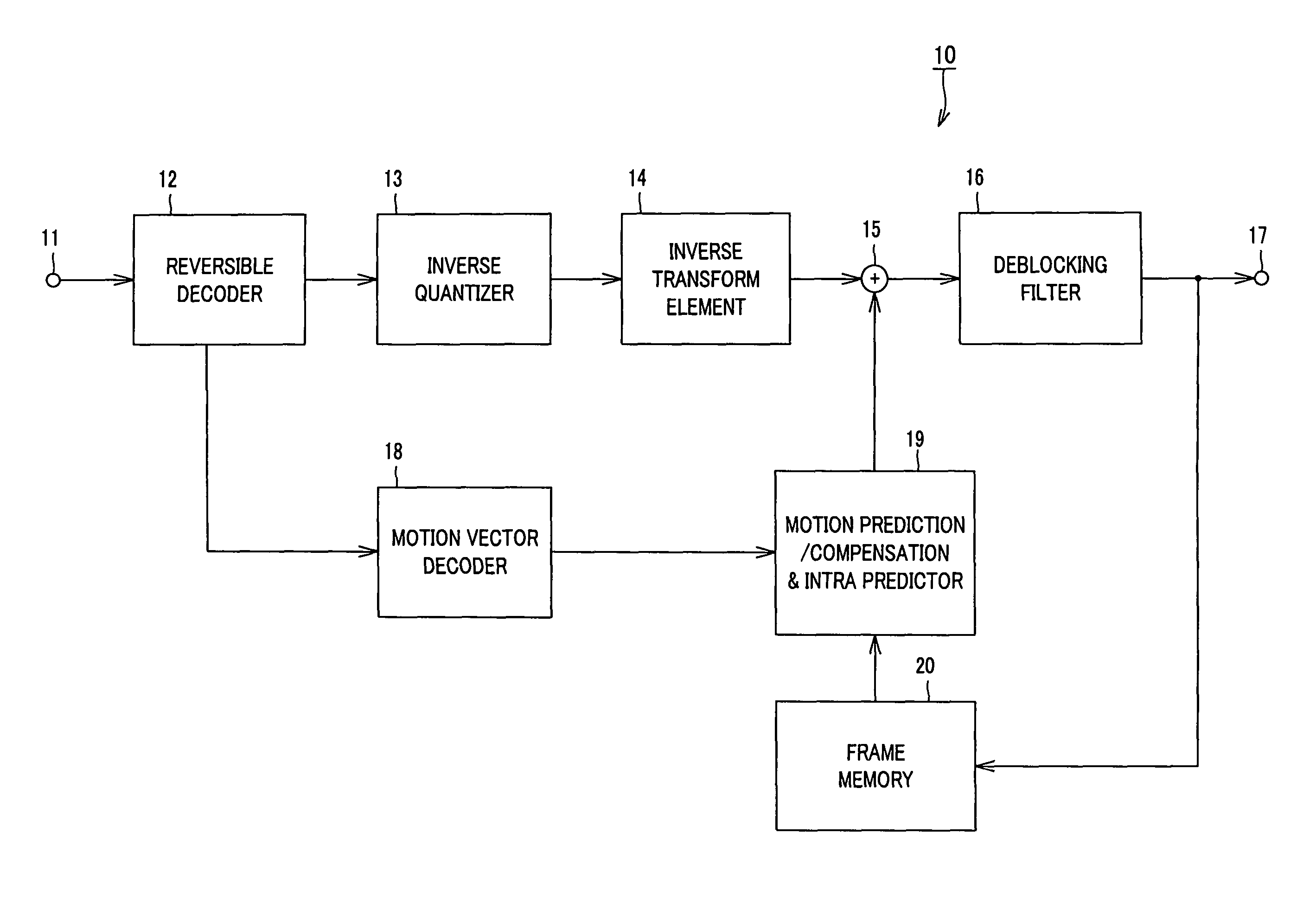
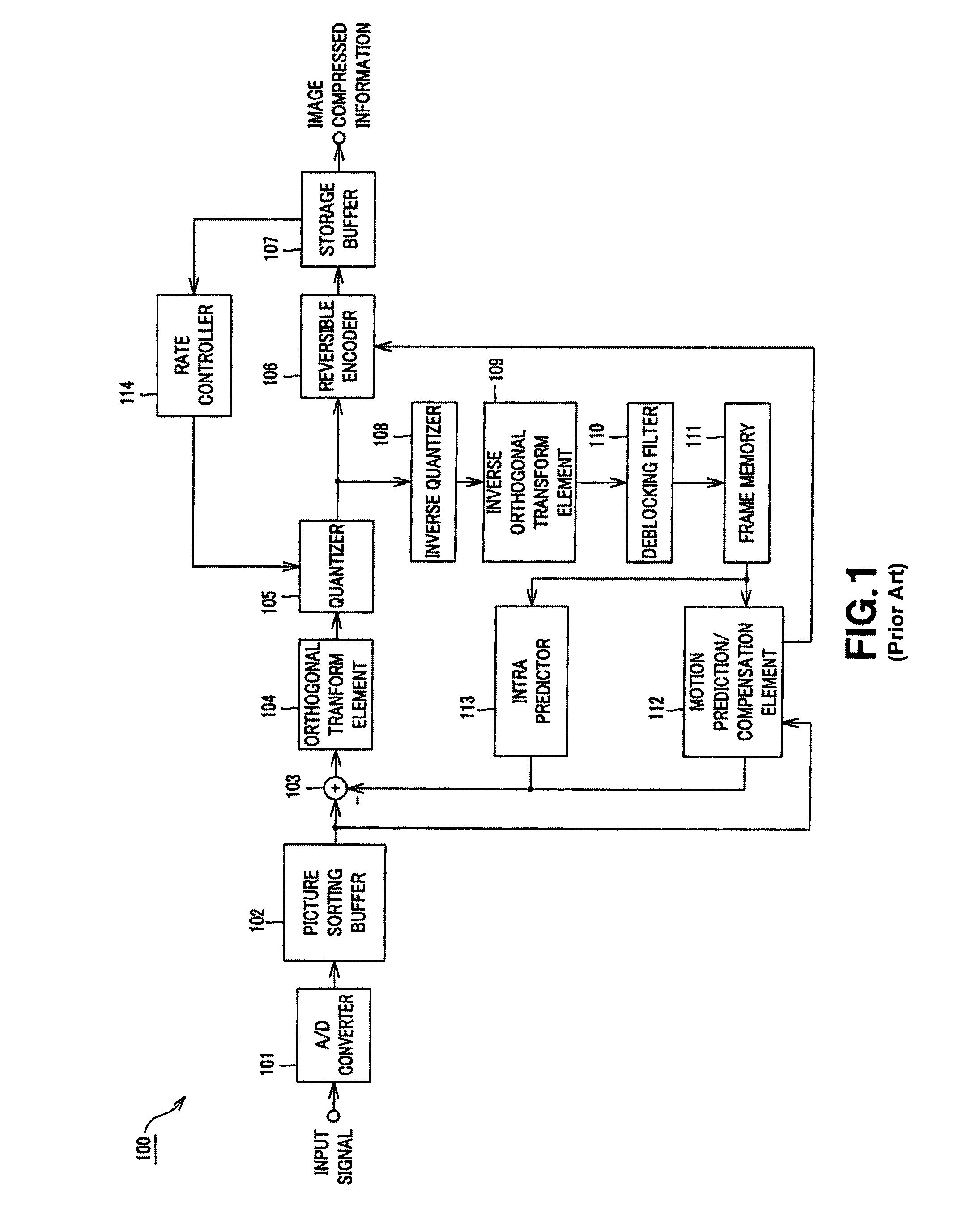
[0059]Then, the third embodiment will be explained. The third embodiment is directed to a local decoder within the previously described image information encoding apparatus 100 as shown in FIG. 1. The local decoder is comprised of inverse quantizer 108, and inverse orthogonal transform element 109. In implementing, at inverse quantizer 123, inverse quantization processing to transform coefficients which have been quantized at the quantizer 105, existence of each transform coefficient is indicated as a flag every processing block of inverse quantization. The processing block consists of 4×4 pixels, 8×8 pixels or 16×16 pixels.

[0060]The inverse orthogonal transform element 109 serves to change invers...

third embodiment

[0061]Accordingly, also in the third embodiment, it becomes unnecessary to perform matrix calculations in length and breadth directions at all blocks consisting of 4×4 pixels, 8×8 pixels or 16×16 pixels. Thus, at the image decoding apparatus, high speed decoding processing can be realized.

[0062]It is to be noted that while the present invention has been described in accordance with certain preferred embodiments thereof illustrated in the accompanying drawings and described in detail, it should be understood by those ordinarily skilled in the art that the invention is not limited to embodiments, but various modifications, alternative construction or equivalents can be implemented without departing from the scope and spirit of the present invention as set forth by appended claims.

Industrial Applicability

[0063]The image decoding apparatus, the image decoding method and the image decoding program according to the present invention are used in receiving, through network media such as sat...


PUM


Abstract

The present invention is directed to an image decoding apparatus adapted for decoding information obtained by implementing inverse quantization and inverse orthogonal transform to image compressed information in which an input image signal is blocked to implement orthogonal transform thereto on the block basis so that quantization is performed with respect thereto, which comprises a reversible decoder (12) for decoding quantized and encoded transform coefficients, an inverse quantizer (13) indicating, as a flag, in inverse-quantizing transform coefficients which have been decoded by the reversible decoder (12), existence of each transform coefficient every processing block of inverse quantization, and an inverse transform element (14) for changing inverse transform processing to be implemented to inverse quantization transform coefficients within processing block by using the flag which has been indicated by the inverse-quantizer (13).

Description

TECHNICAL FIELD[0001]The present invention relates to an image decoding apparatus, an image decoding method and an image decoding program, and more particularly to an image decoding apparatus, an image decoding method and an image decoding program which are used in receiving, through network media such as satellite broadcasting service, cable TV (television) or Internet, etc., or in processing, on storage or memory media such as optical disc, magnetic disc or flash memory, etc., image compressed information (bit stream) compressed by orthogonal transform such as Discrete Cosine Transform or Karhunen-Loeve Transform, etc., and motion prediction / compression like MPEG (Moving Picture Experts Group), H.26x, etc.[0002]This Application claims priority of Japanese Patent Application No. 2003-417336, filed on Dec. 15, 2003, the entirety of which is incorporated by reference herein.BACKGROUND ART[0003]Hitherto, apparatuses in conformity with the system such as MPEG, etc. in which image infor...

Claims


Application Information

Patent Timeline
Patent Type & Authority Patents(United States)
IPC IPC(8): H04N7/12H03M7/30H04N19/127H04N19/124H04N19/136H04N19/44H04N19/50H04N19/503H04N19/51H04N19/60H04N19/61H04N19/625H04N19/91
CPCH04N19/176H04N19/44H04N19/61H04N19/122H04N19/60
Inventor WATANABE, SHINJIIZUMI, NOBUAKI
Owner SONY CORP
Why Eureka
Try Eureka