
Information processing apparatus and method

a technology of information processing and apparatus, applied in the field of apparatus and information processing methods, can solve the problems of discontinuous boundary between adjacent tiles, insufficient memory, visual defects, etc., and achieve the effect of reducing the memory capacity of the wavelet transform process

Inactive Publication Date: 2012-08-21
SONY CORP
View PDF29 Cites 0 Cited by
  • Summary
  • Abstract
  • Description
  • Claims
  • Application Information

AI Technical Summary

Benefits of technology

[0008]However, processing of a large amount of data is avoidable in the case of an image signal, so that the amount of memory will become insufficient at the time of wavelet transform. There, a method of executing the wavelet transform using a small memory size has been considered. For example, Part-1 of JPEG 2000 employs a system that performs a wavelet transform process based on a tile of 128×128 pixels. If the wavelet transform is performed within this limited tile size, the memory capacity can be saved very much.
[0028]According to any embodiment of the present invention, wavelet transform can be performed. In particular, a memory capacity for a wavelet transform process can be reduced.

Problems solved by technology

However, processing of a large amount of data is avoidable in the case of an image signal, so that the amount of memory will become insufficient at the time of wavelet transform.
However, in this method, the boundary between the adjacent tiles is discontinuous.
Thus, an increase in compression ratio in image compression using the wavelet transform may make such a boundary noticeable, resulting in a visual defect.
However, such a method may cause an increase in necessary memory size in response to an increase in number of dividing components in the wavelet transform.

Method used


Image

  • Information processing apparatus and method
  • Information processing apparatus and method
  • Information processing apparatus and method

Examples


first embodiment

1. First Embodiment

[Exemplary Configuration of Wavelet Transformer]

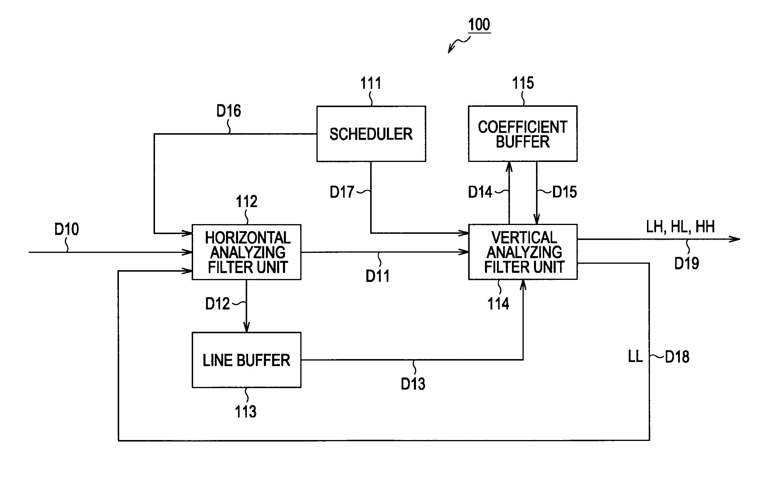
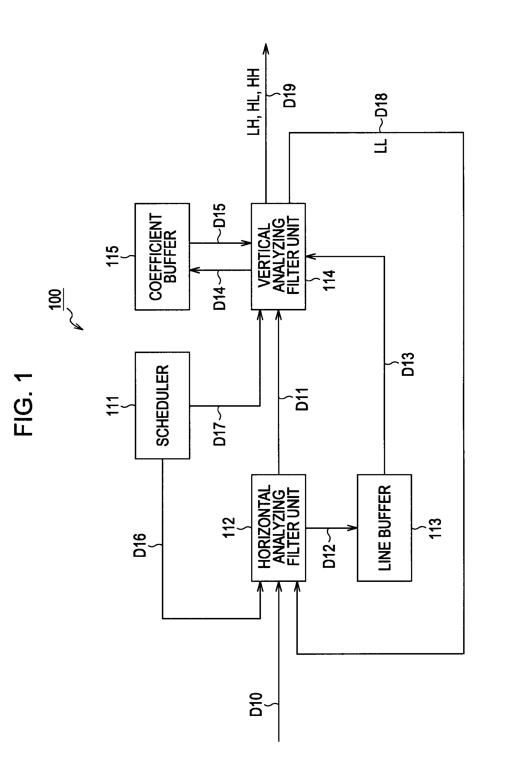
[0053]FIG. 1 is a block diagram illustrating an exemplary configuration of a wavelet transformer according to an embodiment of the present invention. In FIG. 1, the wavelet transformer 100 is configured to perform a wavelet transform process where an analysis filtering process for separating input data into low-pass components and high-pass components is performed on an input image signal in both the horizontal direction and the vertical direction of a screen.

[0054]In other words, the wavelet transform process divides the input data into four components (sub-bands). A first one of these sub-bands is composed of a low-pass component in the horizontal direction and a low-pass component in the vertical direction (hereinafter, such a sub-band will be also referred to as an LL component). A second one of these sub-bands is composed of a high-pass component in the horizontal direction and a low-pass component in the vertic...

second embodiment

2. Second Embodiment

[Explanation of Use of 5×3 Filter]

[0153]The lifting calculation using the 9×7 filter has been described. Alternatively, the lifting calculation may be performed using any of other filters. For example, a 5×3 filter may be used.

[0154]FIG. 15 is a schematic diagram illustrating lifting calculation using a 5×3 filter. In the figure, the uppermost string is an input signal string. Data processing flows from the top to the bottom of a screen to generate outputs of high-pass coefficients and low-pass coefficients from the following equations (5) and (6):

di1=di0−1 / 2(si0+si+10)  (5)

si1=si0+1 / 4(di−11+di1)  (6)

[0155]FIG. 16 is a diagram illustrating an example in which vertical analysis filtering is executed on a group of coefficients in the vertical direction. As shown in FIG. 16, one set of high-pass and low-pass coefficients can be obtained using four lines, from line 1 to line 4.

[0156]Some of coefficients generated in the process of lifting calculation are coefficients...

third embodiment

3. Third Embodiment

[Exemplary Configuration of Encoder]

[0172]The wavelet transformer 100 shown in FIG. 1 may be constructed as a processing part and may be combined with any of other processing unit to form another apparatus. For example, it may be designed as an encoder.

[0173]FIG. 19 is a block diagram illustrating an exemplary configuration of an encoding apparatus using a wavelet transformer 100 shown in FIG. 1 as a processing unit according to an embodiment of the present invention. In FIG. 19, an encoding apparatus 300 is designed to encode an input image signal. The encoding apparatus 300 includes a wavelet transform unit 301, a quantization unit 302, an entropy encoding unit 303, and a rate control unit 304.

[0174]The wavelet transform unit 301 has the same principal configuration as that of the wavelet transformer 100 of FIG. 1. The wavelet transform unit 301 includes a scheduler 111 that controls both a horizontal analysis filter unit 112 and a vertical analysis filter unit ...


PUM


Abstract

An information processing apparatus includes a device for performing horizontal analysis filtering, a device for performing vertical analysis filtering, and a device for horizontal control. The information processing apparatus also includes a first control device. This device allows the device for horizontal control to repetitively perform the horizontal control until the horizontal analysis filtering is performed on all of columns of a processing object line. The information processing apparatus further includes a device for vertical control and a second control device that allows the device for vertical control to repetitively perform the vertical control until the vertical analysis filtering is performed on all of lines.

Description

BACKGROUND OF THE INVENTION[0001]1. Field of the Invention[0002]The present invention relates to an apparatus and a method for information processing. Specifically, the present invention relates an information processing apparatus and a method of information processing to be used in such an apparatus, where the apparatus and the method are capable of reducing the memory usage of a wavelet transformation process in the apparatus.[0003]2. Description of the Related Art[0004]Typical image compression systems, which have been used in the art, include JPEG (Joint Photographic Experts Group) and JPEG 2000 standardized by ISO (International Standard Organization).[0005]In recent years, extensive studies have been conducted for a system in which a combination of filters, high-pass filters and low-pass filters, called as a filter bank is employed to divide an image into a plurality of bands and encoding is then performed for every band. In particular, the wavelet encoding, which is free of a...

Claims


Application Information

Patent Timeline
Patent Type & Authority Patents(United States)
IPC IPC(8): G06K9/36G06K9/46H03M7/30H04N1/41H04N19/426H04N19/60H04N19/63H04N19/91
CPCH04N19/63H04N19/436H04N19/42
Inventor FUKUHARA, TAKAHIROANDO, KATSUTOSHITANAKA, YUUKI
Owner SONY CORP
Learn More