
Storage apparatus and data verification method in storage apparatus

a technology of storage apparatus and data verification method, which is applied in the direction of error detection/correction, instruments, coding, etc., can solve the problem of small error detection code, and achieve the effect of improving the reliability of data in the storage apparatus without increasing overhead

Active Publication Date: 2012-08-21
HITACHI LTD
View PDF14 Cites 8 Cited by
  • Summary
  • Abstract
  • Description
  • Claims
  • Application Information

AI Technical Summary

Benefits of technology

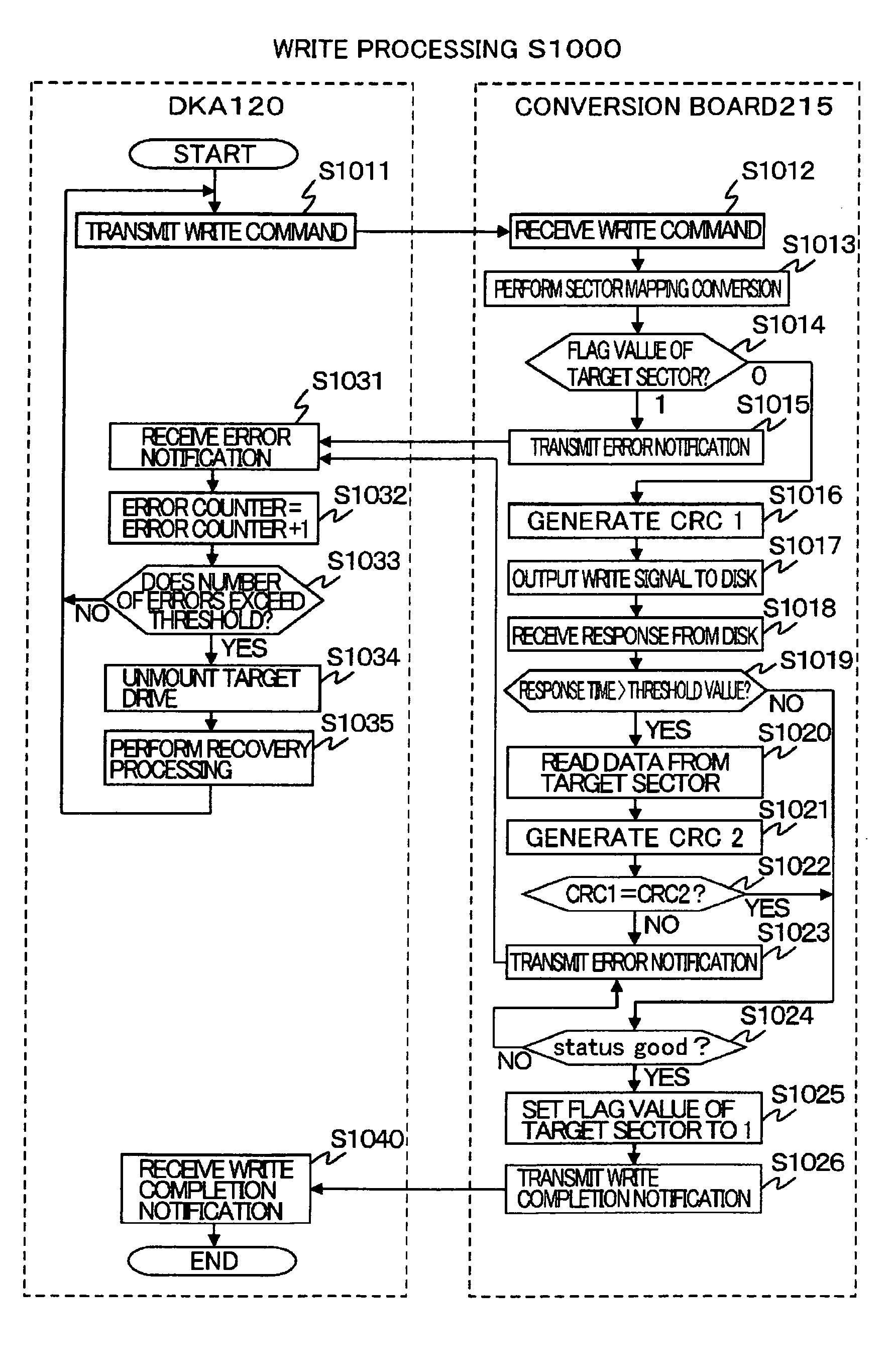
The present invention provides a storage apparatus and method for improving the reliability of data in a storage device without increasing overhead. The storage apparatus includes a CPU and memory, and a storage device for writing and reading data. The apparatus includes a first error detecting code generating part that generates a first error detecting code of write data when a data write request is received. The apparatus also includes a timeout determining part that determines whether or not the response time for writing exceeds a predetermined threshold value. If the threshold value is exceeded, the apparatus generates a second error detecting code and compares it with the first error detecting code. If the two codes do not coincide, the apparatus determines that the data writing was not performed normally and generates a signal indicating the same. The apparatus also includes a write destination status managing part that stores a table that manages whether or not effective data is currently written in each unit storage area of the storage device. The apparatus can detect errors in data writing and prevent malicious data from being written. The method for improving data reliability includes generating a second error detecting code and comparing it with the first error detecting code. The invention provides a solution for improving the reliability of data in a storage device without increasing overhead.

Problems solved by technology

Note that generation of the first error detecting code is performed even when the response time does not exceed the threshold value, but a load generated by the generation processing for the first error detecting code is generally small and overhead for write processing is little affected by this processing.

Method used


Image

  • Storage apparatus and data verification method in storage apparatus
  • Storage apparatus and data verification method in storage apparatus
  • Storage apparatus and data verification method in storage apparatus

Examples


Embodiment Construction

[0045]In the following, description on embodiments of the present invention with reference to the accompanying drawings will be given in detail.

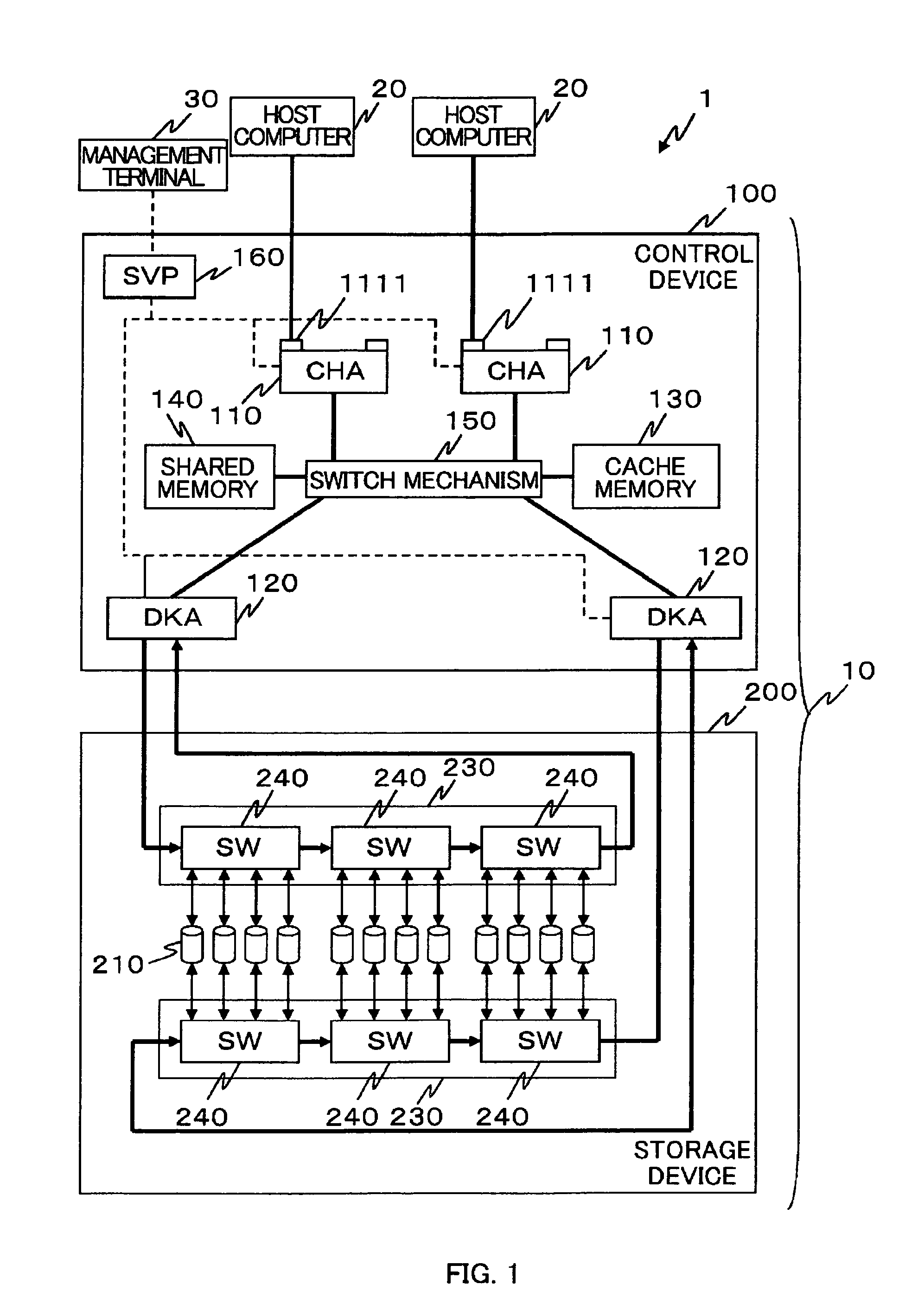
[0046]FIG. 1 illustrates a schematic configuration of a storage system 1 to be explained in the description of an embodiment. As illustrated in the FIG. 1, the storage system 1 includes a storage apparatuS10, a host computer 20, and a management terminal 30.

[0047]The host computer 20 and the storage apparatus 10 are coupled via a communication means 50 such as a LAN (Local Area Network), a SAN (Storage Area Network), the Internet, a public communication network, a dedicated line, and the like. Moreover, the management terminal 30 and the storage apparatus 10 are coupled via communication means 50 such as a LAN, the Internet, and the like. Note that, for example, TCP / IP is used as a LAN communication protocol. As a SAN communication protocol, for example, Fiber Channel is used. When the host computer 20 is a main frame, data transfer is perfo...


PUM


Abstract

When a data write request to a disk drive 210 is received from a host computer 20, a first error detecting code of write data to be written to the disk drive 210 in response to the data write request is generated and stored, write processing of the write data to the disk drive 210 is executed, whether or not response time as time required for the write processing exceeds a predetermined threshold value is determined, data stored in a sector as a writing destination of the write data is read from the sector when the response time exceeds the threshold value, a second error detecting code of the read data is generated, and when the first error detecting code and the second error detecting code are compared with each other and the two codes do not coincide with each other, a signal indicating that the write processing is not normally performed is generated.

Description

TECHNICAL FIELD[0001]The present invention relates to a storage apparatus and a data verification method in the storage apparatus, and more particularly to a technique for improving reliability of data in the storage apparatus without increasing overhead.BACKGROUND ART[0002]In accordance with capacity increase and price reduction of disk drives (hard disk drives), there have been used disk drives with low cost and large capacity such as SATA (Serial ATA) or the like in storage apparatuses such as a disk array apparatus and the like, as well. However, as compared with the conventional SAS (Serial Attached SCSI) drives, these drives with low cost and large capacity do not have sufficient reliability in many cases, and measures to improve reliability of these drives need to be taken in the case of using these drives for the storage apparatus where high reliability is required.[0003]As a mechanism to achieve such purpose Patent Citation 1, for example, describes a technique (hereinafter...

Claims


Application Information

Patent Timeline
Patent Type & Authority Patents(United States)
IPC IPC(8): G06F7/02
CPCG06F11/0727G06F11/0757
Inventor MATSUSHIGE, HIROMI
Owner HITACHI LTD
Learn More