Drill

a drill and drill bit technology, applied in the field of drills, can solve the problems of difficult for such a drill to discharge swarfs at a certain depth, the drill used for drilling a deep hole on a workpiece initially having no holes therein is subject to extremely great loads, and the drill used for drilling holes on the workpiece is subject to extreme loads. , to achieve the effect of reducing the load applied to the drill, prolonging the tool life, and smooth discharg

Inactive Publication Date: 2012-09-04
HONDA MOTOR CO LTD
View PDF37 Cites 8 Cited by
  • Summary
  • Abstract
  • Description
  • Claims
  • Application Information

AI Technical Summary

Benefits of technology

[0010]The present invention has been made in view of the above disadvantages. An object of the present invention is to provide a drill capable of reducing a load applied on the drill when, for instance, a deep hole is bored, thereby prolonging tool lifetime, and enabling swarfs to be smoothly discharged.
[0012]According to the above arrangement, when a deep hole is bored in a workpiece, swarfs can efficiently be discharged from a depth of the deep hole. Thus, clogging of swarfs in the middle of the bored hole can effectively be prevented, and loads on the drill can be reduced, so that the tool lifetime can be prolonged. Further, since the swarf-discharging speed is improved at the rear-side groove, which is longer than the distal-side cutting blade, an increase in resistance due to swarf clogging can be prevented.
[0013]In the above aspect of the invention, it is preferable for a diamond to be provided on the tip end of the blade portion, since dischargeability of swarfs is further improved thereby, and abrasion resistance of the blade tip also is enhanced.
[0014]When the drill is provided with an oil passage, which axially penetrates the drill from the tip end to the rear end thereof, the oil passage constituting a single channel from the shank portion to a section provided with the intermediate groove, and which branches into two channels at the section provided with the intermediate groove, thereby opening at a tip surface of the blade portion at two positions, since only a single channel for the oil passage passes through the axial center of the drill, flow path resistance of the cutting oil within the oil passage can be lowered.
[0015]Further, when the length and torsion angle of the rear-side groove are set larger than the length and torsion angle of the distal-side cutting blade of the blade portion, the size of swarfs generated by the distal-side cutting blade can be reduced, and such swarfs can be discharged efficiently at the rear-side groove. Accordingly, when a deep hole is bored into a workpiece, since swarfs can be discharged efficiently from a depth of the deep hole, swarf clogging in the middle of the hole as the hole is being bored can effectively be prevented, and the load applied to the drill can be reduced, so that the tool lifetime can be prolonged.
[0016]On the other hand, when the torsion angle of the distal-side cutting blade is set greater than that of the rear-side groove, the drill can cut into the workpiece while exhibiting a low cutting resistance. Accordingly, when a cast hole formed on a workpiece is drilled, even if the axial direction of the drill becomes misaligned with the axial direction of the cast hole, the drill can enter straightly along the axial direction of the drill, and the drill is hardly influenced by the orientation of the cast hole. Accordingly, even when the casting accuracy of the cast hole is low, drilling can be conducted securely at a desired position, thereby obtaining high processing accuracy. Further, since oblique entering of the drill into the cast hole on account of such misalignment, which tends to cause bending and damage to the drill, can be effectively avoided, the tool lifetime can be prolonged.

Problems solved by technology

When aluminum-cast engine components requiring deep hole cutting are manufactured in sequence, a great load is applied on the drill utilized for cutting the components.
In particular, a drill used for drilling a deep hole on a workpiece initially having no holes therein is subjected to extremely great loads when drilling the hole in the workpiece.
In addition, it is difficult for such a drill to discharge swarfs at a certain depth of the deep hole.
Accordingly, the drill may be damaged and become clogged by swarfs.
On the other hand, another problem manifests itself when a workpiece with an existing hole is to be bored along the hole.
Accordingly, when such a cast hole is to be bored by a drill, the cutting direction (cutting position) of the drill may become misaligned with the cast hole.
Such misalignment may cause a great load on the drill, thereby lowering the lifetime and processing accuracy of the tool.

Method used


Image

  • Drill
  • Drill
  • Drill

Examples


Embodiment Construction

[0035]A preferred embodiment of a drill according to the invention will be described below in detail with reference to the attached drawings.

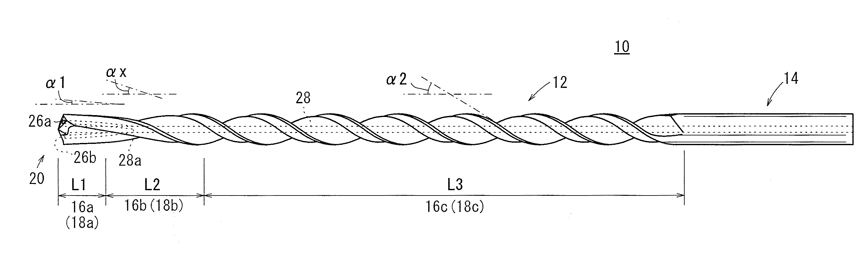
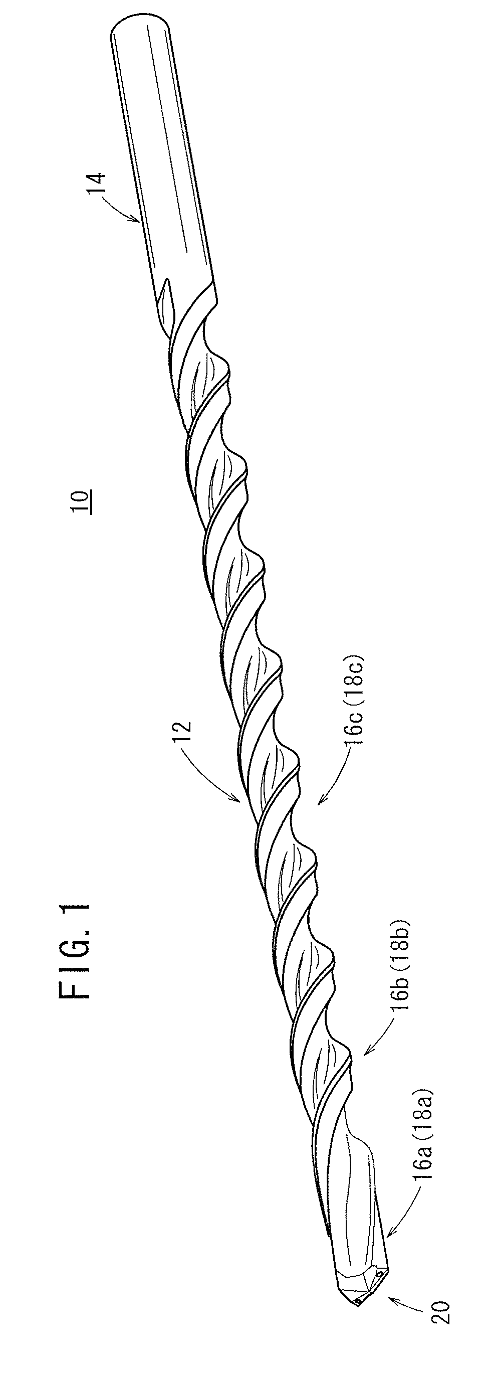
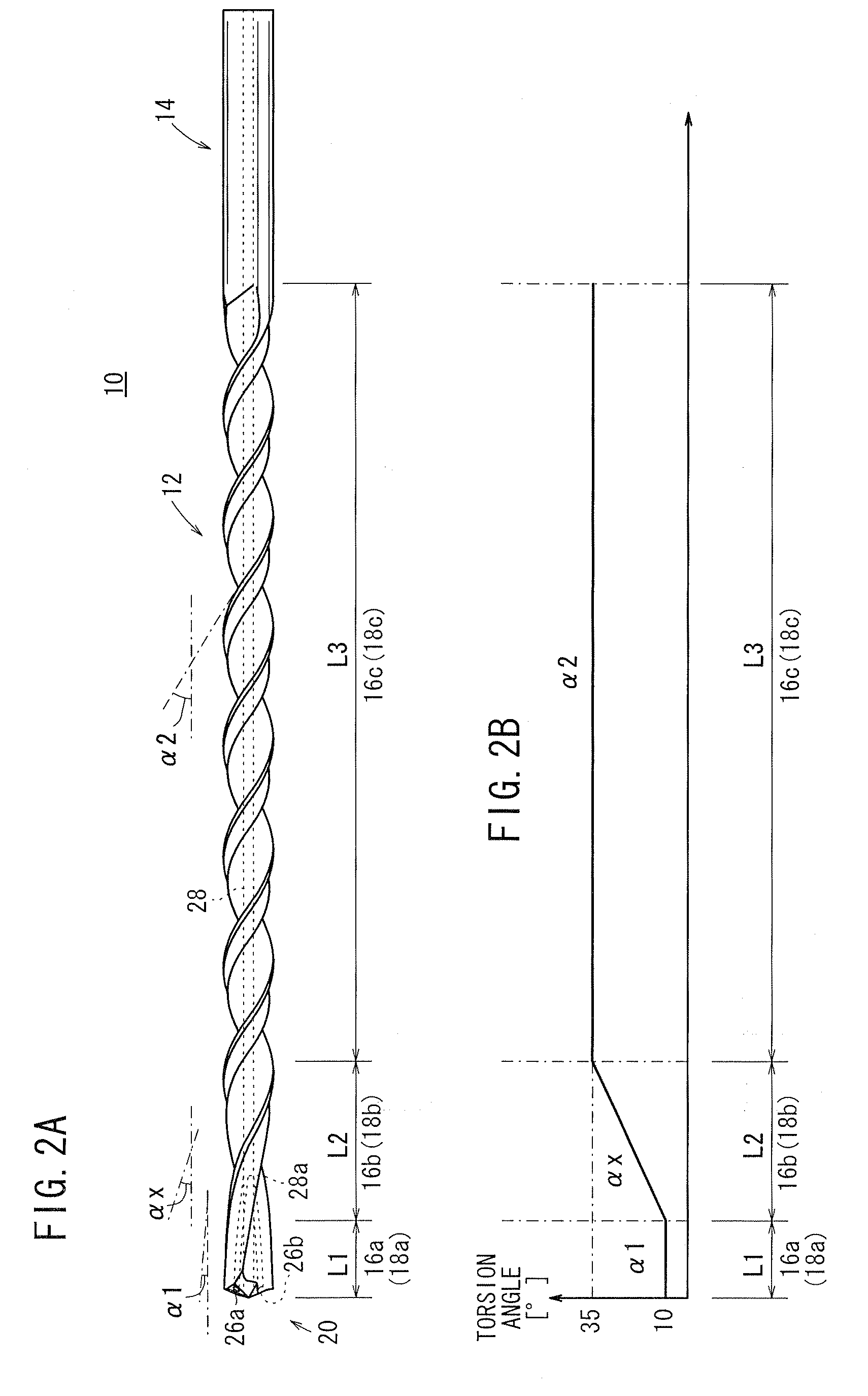
[0036]FIG. 1 is a perspective view showing a drill 10 according to a first embodiment of the present invention. FIG. 2A is a side elevation of the drill 10 shown in FIG. 1. FIG. 2B is an illustration showing a change in a torsion angle of a blade of the drill 10 shown in FIG. 1. The drill 10 according to the present embodiment is suitable for drilling a deep hole in a metal component (workpiece). The workpiece is, for instance, a cylinder block (aluminum-cast engine component). The deep hole herein refers to a hole having a depth five times or greater than an outer diameter of the drill, and for some cases in which the hole is quite deep, having a depth thirty times or greater than the outer diameter of the drill. Cutting such holes applies a great load on the drill (cutting tool). Incidentally, it should be understood that the drill 10 can als...


PUM

PropertyMeasurementUnit
central angleaaaaaaaaaa
torsion angleaaaaaaaaaa

Abstract

A drill includes a blade portion provided with spiral cutting blades along a cutting direction from a tip end to a rear end, and a shank portion formed consecutively on a rear side of the blade portion. The blade portion includes distal-side cutting blades provided from the distal end of the blade portion along the cutting direction and angled at a constant first torsion angle, intermediate grooves formed at a variable torsion angle that varies gradually from the first torsion angle to a second torsion angle, and rear-side grooves formed at the constant second torsion angle. The rear-side grooves are longer than the distal-side cutting blades in the cutting direction, and the second torsion angle is greater than the first torsion angle.

Description

BACKGROUND OF THE INVENTION[0001]1. Field of the Invention[0002]The present invention relates to a drill used, for instance, for drilling a hole in an engine component or the like.[0003]2. Description of the Related Art[0004]When aluminum-cast engine components requiring deep hole cutting are manufactured in sequence, a great load is applied on the drill utilized for cutting the components. Accordingly, a drill suitable for cutting a deep hole has conventionally been used during such processing.[0005]Japanese Utility Model Publication No. 53-038953 discloses a drill suitable for performing deep hole processing on metals, where the torsion angle of the entirety or a part of a blade is consecutively changed, and the torsion angle on the distal side is greater than that on the rear end side of the blade. It is mentioned in this document that such an arrangement improves the bite of the drill as well as the rigidity of the drill.[0006]A drill of this type exhibits a variety of scales of...

Claims


Application Information

Patent Timeline
Patent Type & Authority Patents(United States)
IPC IPC(8): B23B51/02
CPCB23B51/02B23B51/06B23B2222/04B23B2251/046Y10T408/81B23B2251/424B23B2251/443Y10T408/455Y10T408/9097B23B2251/422B23B51/063B23B51/066
Inventor ONOSE, JUNYAFUKUSHIMA, HIROYUKIHAKOZAKI, MASAHIRONOMURA, SHIGEMITSUKONNO, TAKAYUKI
Owner HONDA MOTOR CO LTD
Why Eureka
Try Eureka