Power amplifier protection circuit

a protection circuit and power amplifier technology, applied in the protection circuit arrangement of amplifiers with semiconductor devices only, amplifiers with semiconductor devices, etc., can solve the problems of damage to the power amplifier, constructive or destructive interference, and the antenna impedance can vary, so as to maintain stability

Active Publication Date: 2012-09-04
SKYWORKS SOLUTIONS INC
View PDF11 Cites 21 Cited by
  • Summary
  • Abstract
  • Description
  • Claims
  • Application Information

AI Technical Summary

Benefits of technology

[0010]Another object of the present invention is to provide a circuit for protecting a power amplifier. The circuit includes a protection circuit, connected as a negative feedback loop around the power amplifier, a detector circuit, a driver circuit and an attenuator circuit. The detector circuit according to an embodiment of the present invention is configured to detect voltage peaks at an output of the power amplifier and provide a driver signal when the output exceeds a predefined threshold. The driver circuit is configured to filter the driver signal and provide a filtered signal. The driver circuit adjusts gain and phase margin of the negative feedback loop to maintain stability. The attenuator is configured to receive the filter signal from the driver circuit and adjust an input to the power amplifier, wherein adjustment in the input to the power amplifier causes the output voltage to fall below the predefined threshold and thus protects the power amplifier from damaging effects of the voltage peaks.
[0011]Another object of the present invention is to provide a method for protecting a power amplifier from damage due to breakdown. The breakdown is caused by high voltage peaks at an output of the power amplifier. The method comprises the steps of detecting the output of the power amplifier and providing a negative feedback signal at an input of the power amplifier. The step of providing the negative feedback signal further comprises providing a driver signal from a detector circuit when an output of the power amplifier exceeds a predefined threshold, filtering the driver signal to provide a filtered signal and attenuating the filtered signal to provide the negative feedback signal. The negative feedback is configured to reduce the output signal from the power amplifier to a level below the predefined threshold.

Problems solved by technology

However, the impedance of antenna can vary due to environmental factors or antenna damage.
This causes a mismatch between the antenna and the PA, as a result standing waves are formed by forward and reflected waves to and from the antenna giving rise to constructive or destructive interference.
High values of VSWR indicate a load mismatch, and load mismatch can cause damage to the power amplifier due to voltage breakdown.
Additionally, other factors, such as power supply over voltage, temperature and excessive input drive demand the PA to be highly rugged.
However, increase in the breakdown capability of the PA comes at the expense of performance factors such as Power Added Efficiency (PAE).
However, an isolator adds some series loss, increases cost and grows the solutions footprint.
A matching circuit cannot prevent voltage peaks at the output of a PA from causing damage to the PA due to voltage breakdown.

Method used


Image

  • Power amplifier protection circuit
  • Power amplifier protection circuit
  • Power amplifier protection circuit

Examples


Embodiment Construction

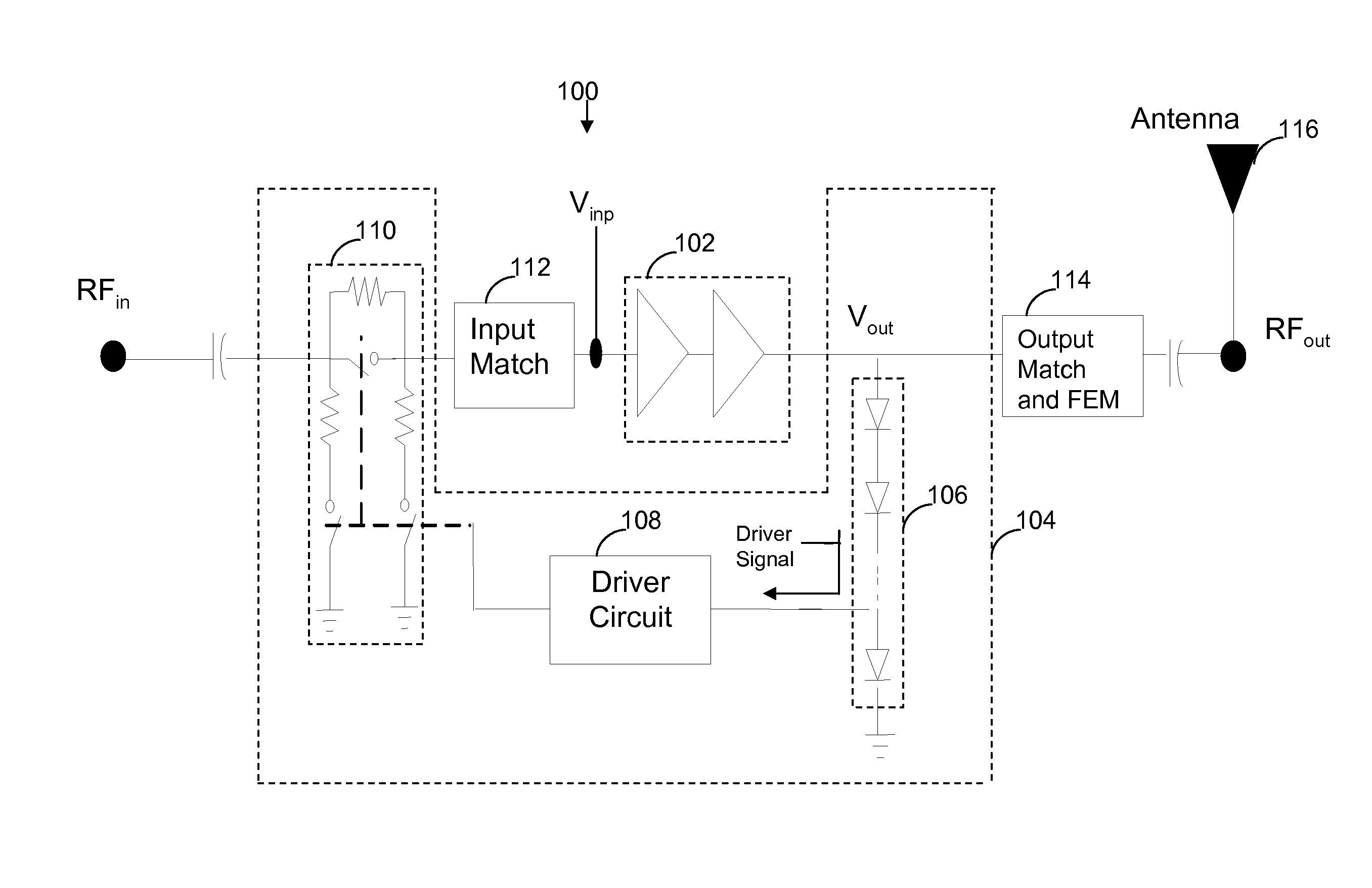
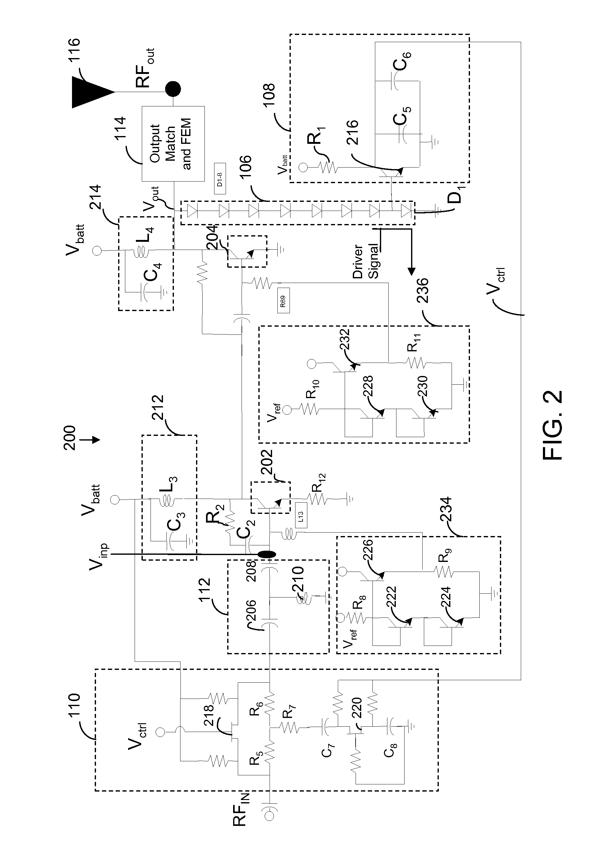
[0017]Various embodiments of the invention provide a protection circuit for a Power Amplifier (PA) for preventing damage to the PA due to voltage breakdown. The protection circuit comprises a negative feedback loop coupled to the PA for providing an attenuated input voltage to the power amplifier, when an output voltage of the power amplifier exceeds a predefined threshold. The negative feedback loop comprises a detector circuit, a driver circuit and an attenuator circuit, which reduces the level of an input signal to the power amplifier

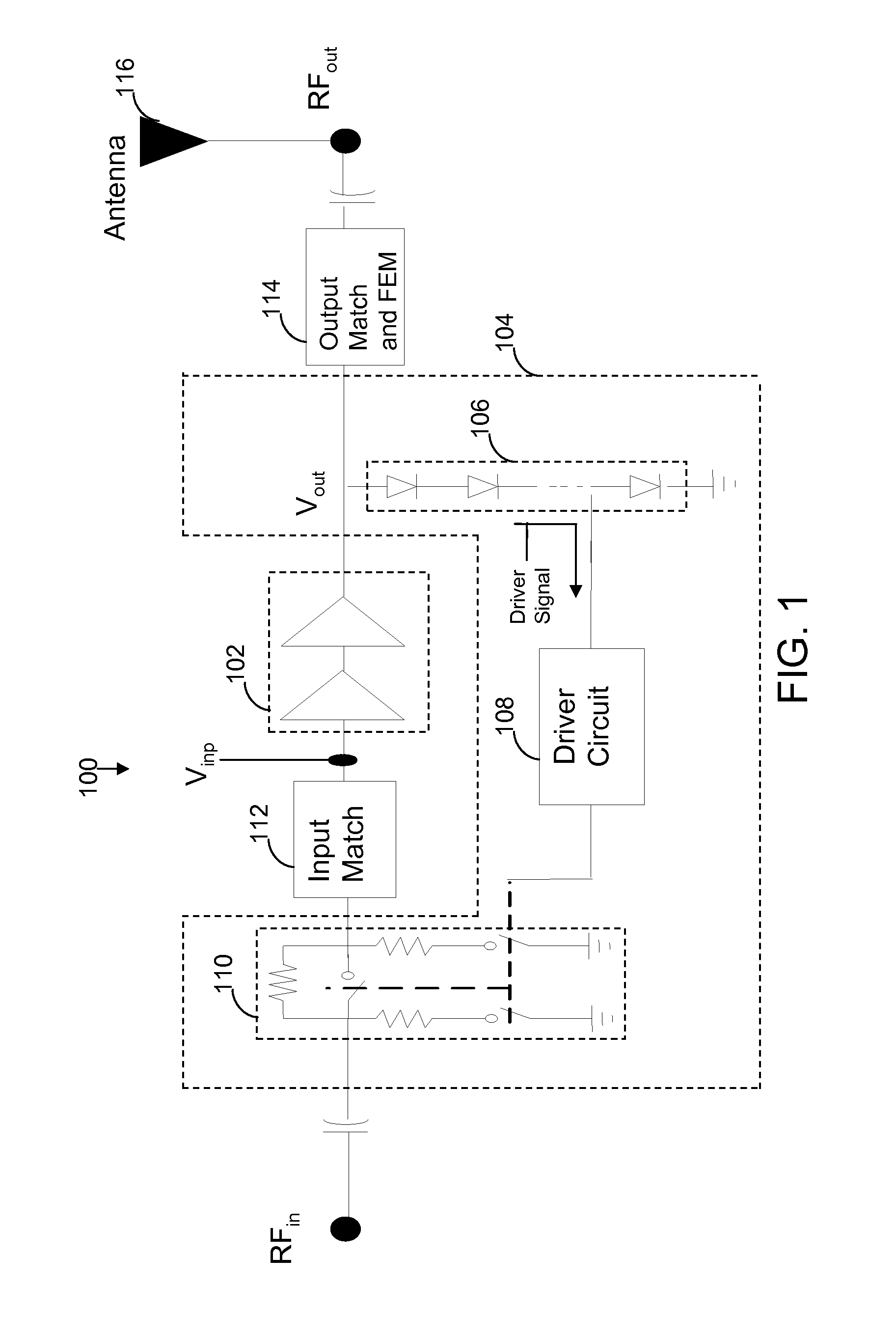
[0018]FIG. 1 is a simplified schematic of a circuit 100 for a PA 102, in accordance with an embodiment of the invention. Circuit 100 includes a negative feedback loop 104. Negative feedback loop 104 further includes a detector circuit 106, a driver circuit 108 and an attenuator circuit 110.PA 102 amplifies a low level radio frequency signal (RFin) at the input of an input matching circuit 112. Ideally, a PA should be completely matched to the antenna...


PUM


Abstract

A protection circuit for a power amplifier connected as a negative feedback loop around the power amplifier. The negative feedback loop comprises a detector circuit, a driver circuit and an attenuator circuit. The detector circuit receives output voltage from the power amplifier and generates a signal when the output voltage exceeds a predefined threshold. The driver circuit filters the signal received from the detector circuit to maintain feedback loop stability and adjusts the feedback loop bandwidth and gain to provide a filtered signal. The attenuator circuit receives the filtered signal and attenuates the input voltage of the power amplifier to reduce the output voltage of the power amplifier to a level below the predefined threshold.

Description

BACKGROUND OF THE INVENTION[0001]The present invention generally relates to the field of power amplifiers used in wireless systems. More specifically, it relates to a protection circuit for wireless handset amplifier circuits.[0002]A wireless system requires an air interface or antenna to transmit radio wave energy. Wireless systems such as mobile systems, which encompass systems based on Global System for Mobile Telecommunication (GSM) / EDGE standards, and the like, have to handle high power. The high power requirements of mobile systems illustrate the need for conversion of a low-power radio frequency signal to a high power signal. For this purpose, a Power Amplifier (PA) is used for driving the antenna in a mobile system. Ideally, a PA should be completely matched to the antenna so that maximum amount of energy is transmitted. The matching of an antenna and the corresponding PA is expressed in terms of a Voltage Standing Wave Ratio (VSWR), which is the ratio of maximum to minimum ...

Claims


Application Information

Patent Timeline
Patent Type & Authority Patents(United States)
IPC IPC(8): H02H7/20
CPCH03F1/34H03F1/52H03F3/245H03F2200/211
Inventor OSIKA, DAVIDLOTT, JOELREYES, JULIO
Owner SKYWORKS SOLUTIONS INC
Why Eureka
Try Eureka