
Channel estimation using common and dedicated pilots

a channel estimation and dedicated pilot technology, applied in the field of receiver apparatus and channel estimation, can solve the problems of limited accuracy of channel estimation approach relying on dpcch channel, inability to use in the presence of beamforming, and inability to adapt to the physical channel cpich transmission, etc., to achieve enhanced channel estimation and better performance

Inactive Publication Date: 2012-09-04
ST ERICSSON SA
View PDF11 Cites 4 Cited by
  • Summary
  • Abstract
  • Description
  • Claims
  • Application Information

AI Technical Summary

Benefits of technology

[0012]It is an object of the present invention to provide an enhanced channel estimation scheme for better performance and various receiver types.
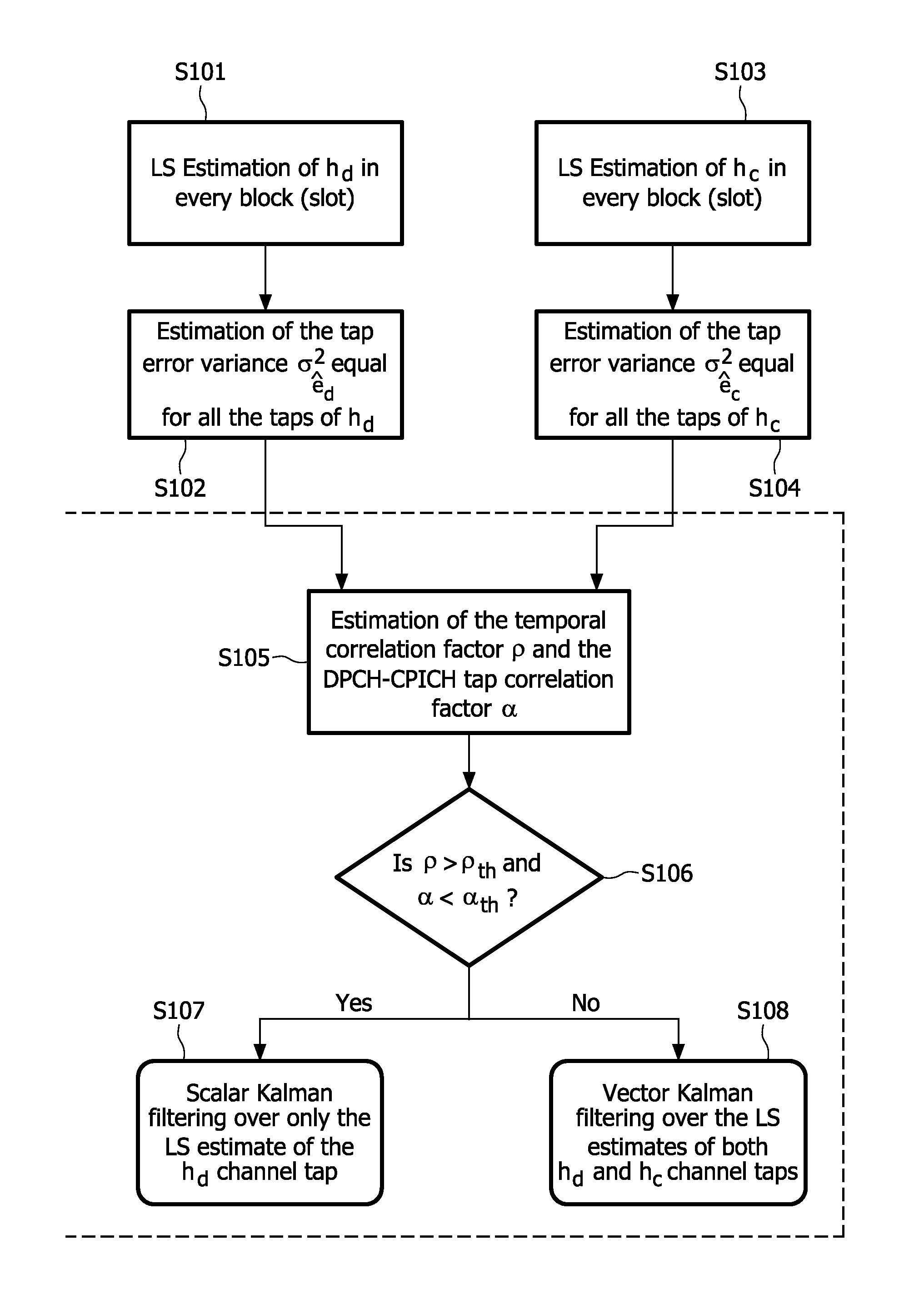
[0014]Accordingly, at least one of spatial and temporal correlations of the at least two pilot sequences are exploited to obtain an optimized channel estimation performance. Knowledge of path delays and beamforming parameters is not required. The proposed estimation mechanism is suitable for all types of receivers including discrete time Rake and particularly equalizers in FIR form and the interference cancellation schemes. The at least two pilot sequences may comprise a first pilot sequence broadcast in a common pilot channel, and a second pilot sequence broadcast in a dedicated pilot channel. The joint evaluation of common and dedicated pilot sequences provides the advantage that limitations in use of one of the dedicated and common pilot sequences can be enhanced by exploiting the respective other sequence.

Problems solved by technology

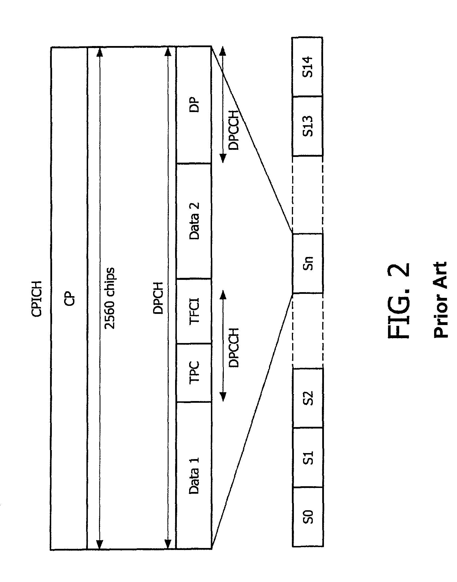
While transmit beamforming is to be employed for the transmission of the physical channel DPCH, it is not suited for the physical channel CPICH transmission that is to be uniformly broadcasted in time and space (i.e. in all directions) to all users.
The channel estimation approach relying on the DPCCH channel has limited accuracy due to the reduced number of dedicated pilot symbols DP per slot.
However, it cannot be used in the presence of beamforming.
However, they assume that they have perfect a priori knowledge of the path delays and the channel associated with the DPCH is identical to the one associated with the CPICH, which is not the case when there is beamforming.

Method used


Image

  • Channel estimation using common and dedicated pilots
  • Channel estimation using common and dedicated pilots
  • Channel estimation using common and dedicated pilots

Examples


Embodiment Construction

[0027]In the following, the preferred embodiment will be described based on a receiver of a UE according to the UMTS standard.

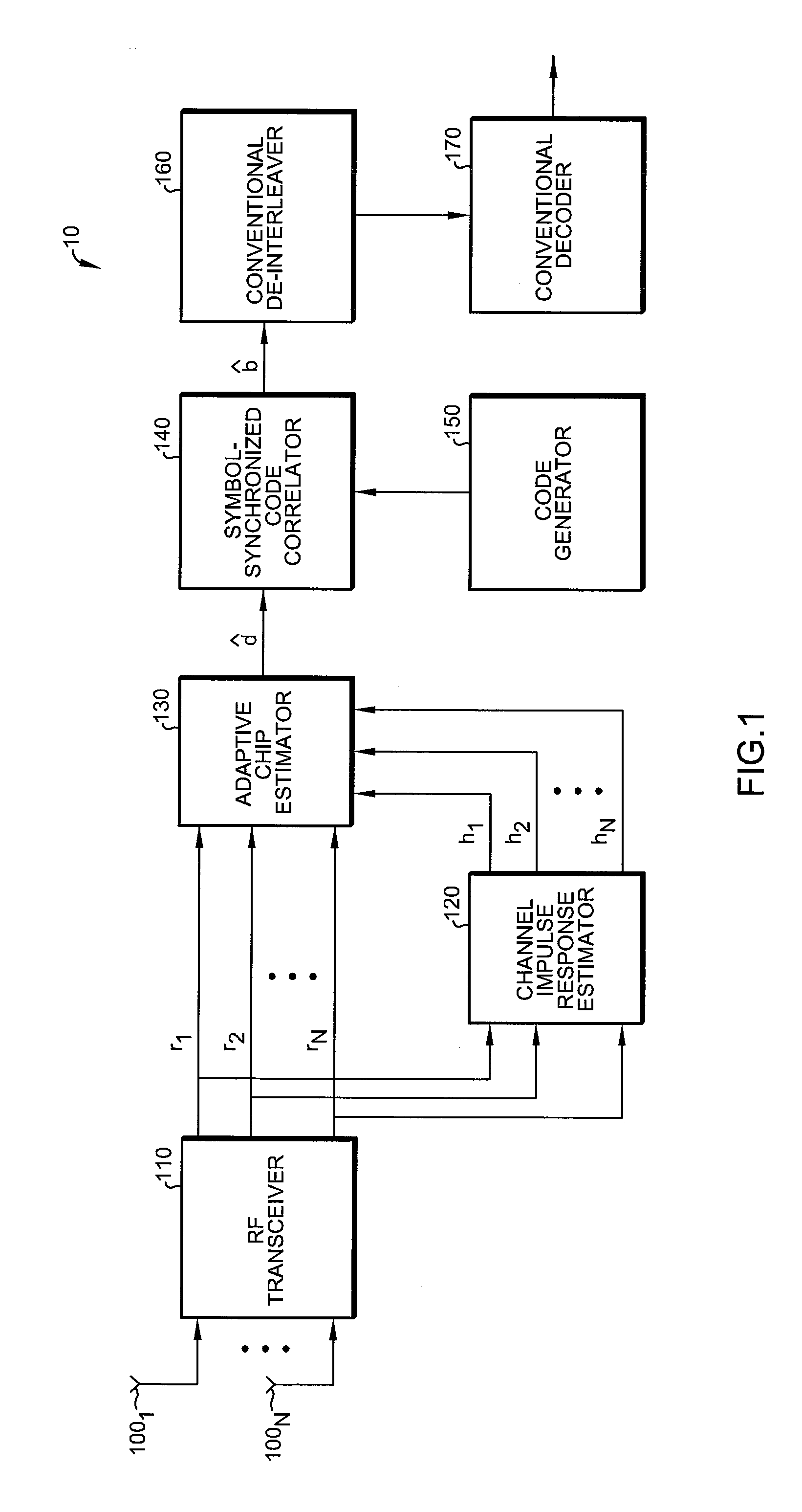
[0028]FIG. 1 shows a schematic block diagram of the receiver 10 in which the preferred embodiment of the present invention can be implemented. The receiver 10 has an adaptive interference suppression algorithm, which is based on channel equalization and suitable for synchronous CDMA (Code Division Multiple Access) systems using orthogonal spreading codes with code scrambling. In particular, the receiver 10 is not obliged to have any training sequence or training information for the adaptation of the equalization. It only needs initialization weights obtained from a channel estimation scheme.

[0029]According to FIG. 1, at least one antenna 1001 to 100N receives signals from a telecommunications channel. The signals are coupled to a conventional RF transceiver 110 including an analog-to-digital (A / D) converter. The conventional RF transceiver 10 may optionally p...


PUM


Abstract

The present invention relates to a receiver apparatus and method of channel estimation in a telecommunication system which provides at least two pilot sequences, and to a computer program product. Channel estimation is achieved by estimating channel taps separately for each of the at least two pilot sequences in every transmission block, and for applying estimated channel taps obtained from the estimation to at least one of a temporal and spatial filtering or combining operation to refine the channel estimate. Accordingly, temporal correlations and cross-correlations of the at least two pilot sequences are exploited without requiring knowledge of path delays and beamforming parameters.

Description

CROSS-REFERENCE TO RELATED APPLICATIONS[0001]The present application is a U.S. national filing of PCT / IB2007 / 051299 filed Apr. 11, 2007, which is incorporated herein in its entirety by this reference.FIELD OF THE INVENTION[0002]The present invention relates to a receiver apparatus and method of channel estimation based on a combined exploitation of dedicated and common pilot sequences. As an example, the present invention relates to a receiver apparatus and channel estimation method for a user-dedicated downlink channels in the Universal Mobile Telecommunications System (UMTS).BACKGROUND OF THE INVENTION[0003]A UMTS communication system comprises at least a base station (BS) referred to as Node B and a mobile phone terminal referred to as user equipment (UE) throughout the document. Both the Node B and the UE comprise a transmitter and a receiver. The Node B sends signals by means of its transmitter to the UE receiver in the downlink. The UE sends signals by means of its transmitter...

Claims


Application Information

Patent Timeline
Patent Type & Authority Patents(United States)
IPC IPC(8): H03K9/00H04L27/00
CPCH04L25/0226H04L25/0228
Inventor BASTUG, AHMETMONTALBANO, GIUSEPPE
Owner ST ERICSSON SA
Learn More