Dual wall axial flow electric heater for leak sensitive applications

a technology of leakage and electric heater, which is applied in the direction of liquid transfer devices, lighting and heating equipment, and immersion heating arrangements, etc., can solve the problems of increased risk of leakage, limited use, and increased probability of leakage, so as to reduce the risk of leakage, improve safety, and low cost of ownership

Active Publication Date: 2012-09-04
LORD LTD LP
View PDF9 Cites 7 Cited by
  • Summary
  • Abstract
  • Description
  • Claims
  • Application Information

AI Technical Summary

Benefits of technology

[0020]Objects of the embodiments of the invention include, but are not limited to, providing improved safety by reducing the risk of leaks and by pre-release leak detection, low cost of ownership, a variable flux along the heater length, a reduction in hot spots which can increase corrosion rates, and a reduction or elimination of overheating of the heater.
[0027]A further leak protection comprises a conduit between the primary and secondary tube plate designed to withstand the process pressure and to provide a pressure transmitter and alarm to both contain a leak through a protective tube and to provide an alarm that a leak has occurred. It is then possible to temporarily take the unit out of service while an emergency repair is conducted by removing the heater rod and plugging the leaking protective tube as is standard practice with shell and tube heat exchangers. It is further preferred that each heater rod is individually pressure sealed to the secondary tube plate so that it may be removed and replaced while in service if the heater rod fails and that the inside of the protective tube and the outside of the heater rod have a high emissivity coating to enhance radiation transfer between them. Further cost reduction can be obtained by use of a second tube bundle inserted at the opposite end to the first bundle. The additional design flexibility of variable flux can be obtained by increasing, or varying the diameter of the protective tube. A thermowell may be inserted in the center of the heater rod or the protective tube to directly measure the heater temperature at various locations.

Problems solved by technology

However, electrical heaters present certain limitations compared to shell and tube heat exchangers.
Both types of design will release materials to atmosphere in the event of a leak in the tubes and will have to be shutdown for repairs.
With corrosive materials the probability of the leak increases: many corrosive materials are also toxic thus providing a serious health hazard.
Despite this leak potential, leak detection systems are not usually provided to warn the operator.
Corrosion increases rapidly with temperature so any hot spots on the tube will corrode much faster.
With the immersion design some areas may have poor flow and are thus unable to remove the heat and become hot spots.
This is particularly the case with corrosive gases which are more difficult to heat.
Such changes in direction create areas of low flow in the transition from cross flow to axial flow which can create hot spots.
Thus it is not possible to use standard shell and tube designs with electrical heat as the typical cross flow baffles cause hot spots.
Also it can be seen that the failure of one heater tube or wire requires removal of the entire assembly to repair the failure.
This adds to the cost of operation as is discussed in U.S. Pat. No. 7,318,735.
However, the solution presented therein also has problems in that the unit must be shutdown and dismantled in order to weld on the header plate.
A further problem with corrosive materials is that they typically have an upper temperature which should not be exceeded.
This then limits the flux which may be used at the hot end of the heater.
However, since heaters typically have a single flux this can mean there is also a low flux at the cold end and thus the overall heater is much bigger.
One solution to this is a variable flux rate where the flux is higher at the cold end than at the hot end, but such heaters are more expensive to make and are not readily available.
A further disadvantage is the absence of methods to measure the heater temperature and thus be aware if a heater is overheating.
It is possible to put separate thermowells through the header plate but this requires more room and additional penetrations of the plate and each thermowell only measures the point on the heater that it contacts.

Method used


Image

  • Dual wall axial flow electric heater for leak sensitive applications
  • Dual wall axial flow electric heater for leak sensitive applications
  • Dual wall axial flow electric heater for leak sensitive applications

Examples


Embodiment Construction

[0046]While a descriptions of a preferred embodiment is provided herein, it is to be understood that the present invention may be embodied in various forms. Therefore, specific details disclosed herein are not to be interpreted as limiting, but rather as a basis for the claims and as a representative basis for teaching one skilled in the art to employ the present invention in virtually any appropriately detailed system, structure or manner.

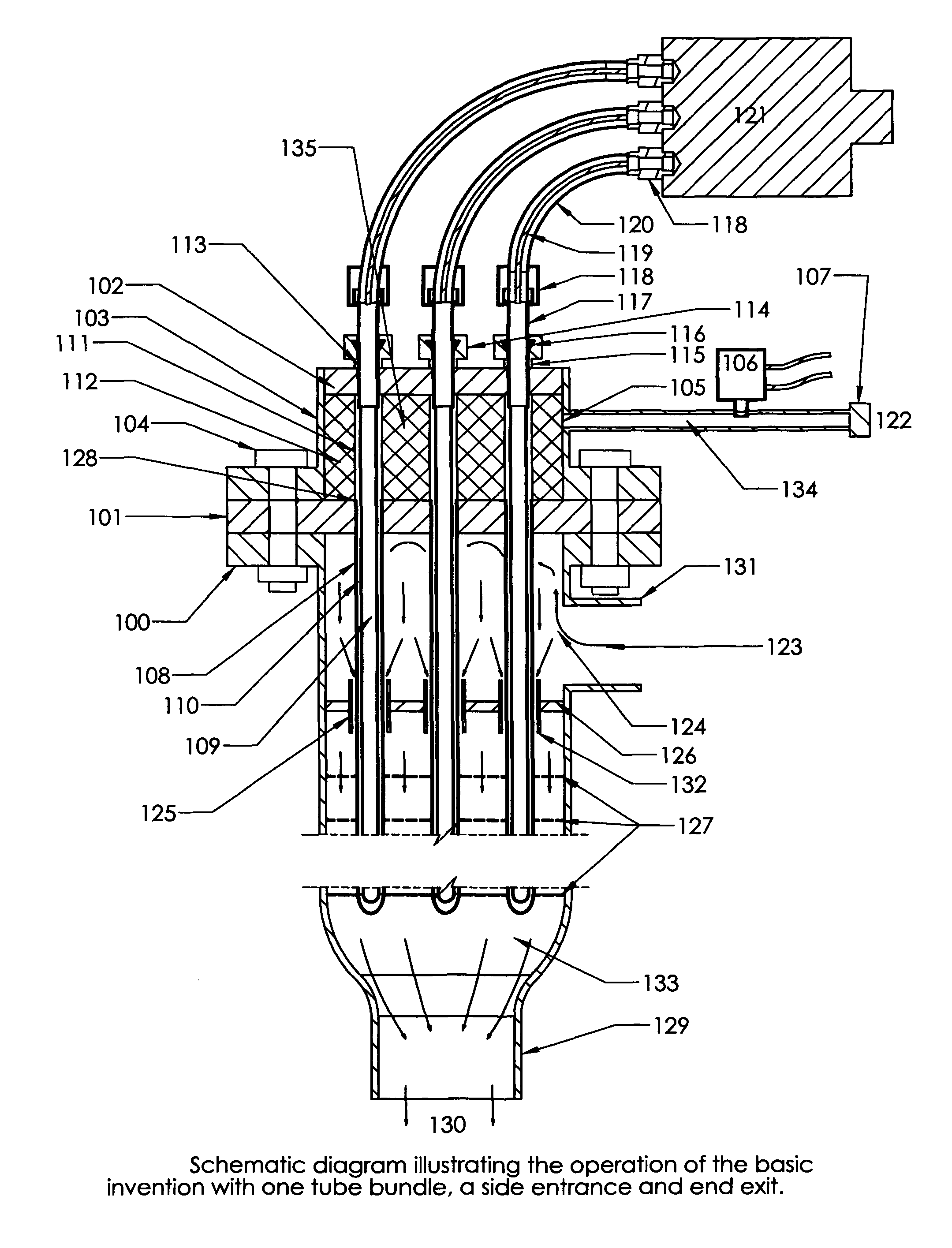
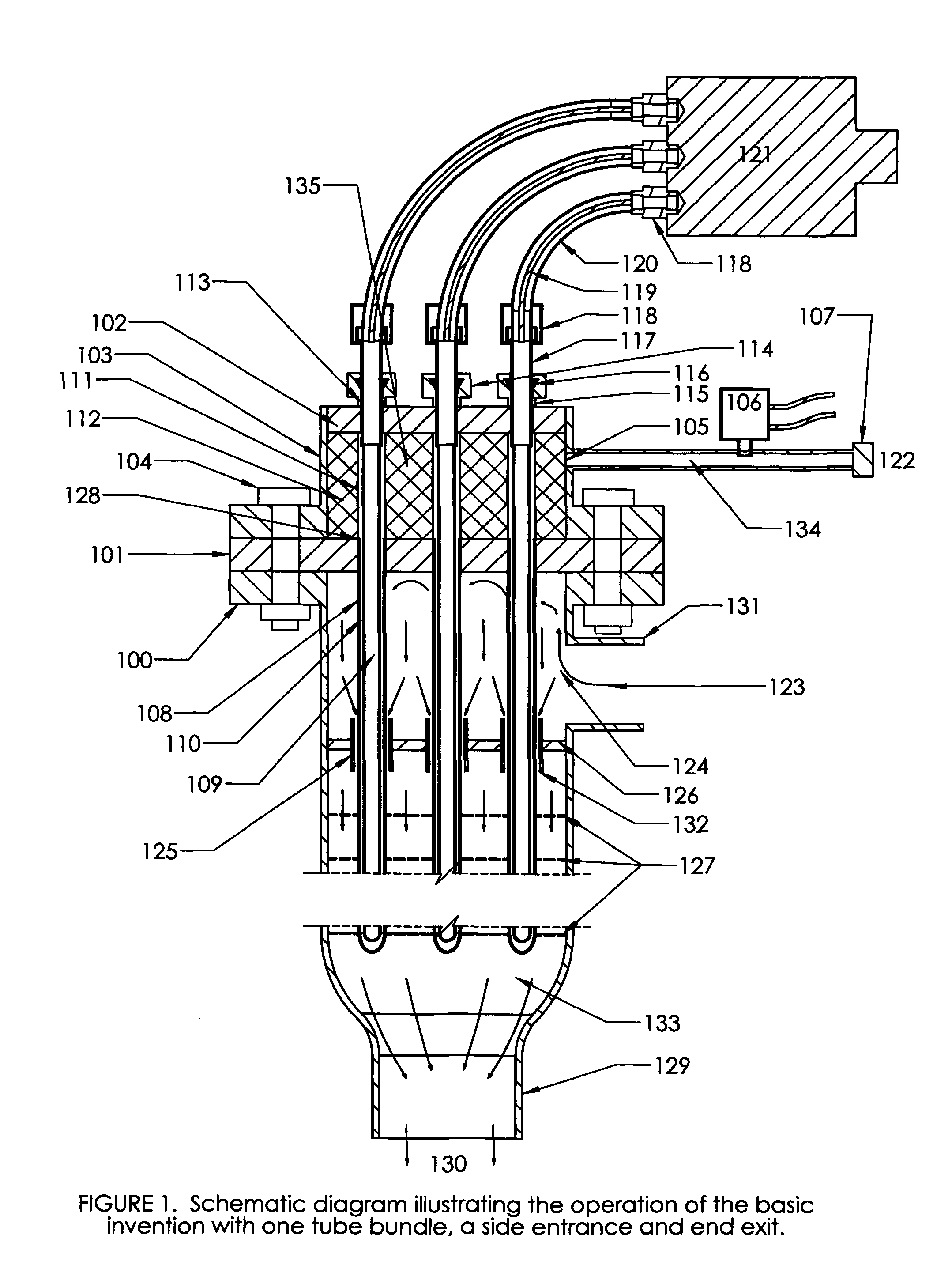
[0047]FIG. 1 is a schematic diagram of the concept of the basic embodiment of the invention. The upper portion includes a dual tube sheet arrangement similar to dual tube sheets used in conventional shell and tube heat exchangers. To avoid cross-contamination between the heat exchange fluid and the fluid being heated, since there is only one fluid being heated, the tube sheets constitute the top of the dual wall. The secondary protection consists of the plenum 135 between the primary tube sheet 101, which is connected to the secondary tube sheet 1...


PUM


Abstract

A dual wall axial flow electric heater for leak sensitive applications provides an improved corrosion and leak resistant assembly and includes protective tubes over electrical heater rods, double tubesheets spaced apart by a plenum and leak detectors positioned to sensor leaks through the walls of the protective tubes. The design includes the option of two or more tube bundles with each inserted into opposite ends of a shell surrounding the tube sheets and heaters. The design provides ease of maintenance since each heater rod can be replaced independently while the unit is in service. Variable heat flux is provided from standard single flux heater rods by providing protective tubes of varying diameters. A built-in thermowell is provided to allow the rod temperatures to be monitored directly. Hot spots are avoided by the use of turning baffles and vibration is avoided by use of spider baffles to support the tubes.

Description

[0001]This invention relates generally to the field of electric heating of fluids and more specifically to a Dual Wall Axial Flow Electric Heater for Leak Sensitive Applications.DEFINITIONS[0002]For the purposes of this disclosure the definitions of certain terms are set forth below[0003]A “heater rod” is an assembled heater in a swaged metal jacket which is inserted in a protective tube The assembled heater comprises three zones, namely the lead wire zone which extends outward from the cold junction, which has low heat output, a second zone comprising the heater proper, which has high heat output and a third zone comprising the cold toe, which has low heat output.[0004]“Tie Rods” comprise multiple long metal rods used to fasten the baffle assembly together. One end of the tie rod is threaded into a tube sheet and the other end is secured, for example by nuts. The baffles have holes in them that match the tie rod positions and are slid over the tie rods and positioned longitudinally...

Claims


Application Information

Patent Timeline
Patent Type & Authority Patents(United States)
IPC IPC(8): F24H1/10A47J31/00
CPCF24H1/225F24H3/081H05B3/42F24H9/0021F24H9/0063F24H9/0015F24D2200/08F24H9/20F24H1/10
Inventor LORD, STEPHEN MICHAELLUND, KURT
Owner LORD LTD LP
Why Eureka
Try Eureka