Plastic pipe cutting tool

a cutting tool and plastic pipe technology, applied in the field of cutting tools, can solve the problems of large space occupation, large cutting knife itself, heavy and high-cost, etc., and achieve the effects of small volume, small and light, and convenient portability

Inactive Publication Date: 2012-09-11
NINGBO JF TOOLS INDAL
View PDF12 Cites 10 Cited by
  • Summary
  • Abstract
  • Description
  • Claims
  • Application Information

AI Technical Summary

Benefits of technology

[0006]One of the primary objectives of the present invention is to provide an electric plastic pipe cutting tool that can decrease labor intensity, and is light and easy-carried.
[0007]Another objective of the present invention is to provide a plastic pipe cutting tool having a simple and practical structure, occupies small space and being capable of fast knife-quitting.

Problems solved by technology

The Chinese patent No. 200720109332.9 disclosed a “rotary cutting knife convenient to cut large diameter pipe”, but there are deficiencies that the cutting is laborious due to manual operation, and the cutting knife itself has a complicate structure, occupies large space, and is heavy and high-cost, therefore a further improvement is needed.
The Chinese patent No. 2007201110120.2 disclosed a “forcipate PVC pipe cutting knife with automatic knife-quitting structure”, but there are also such deficiencies, that is, the cutting is laborious due to manual operation, and the cutting knife itself has a complicate structure, and is high-cost.
In particular the rollback mechanism was not so compact and effective, and therefore a further improvement is also needed.

Method used


Image

  • Plastic pipe cutting tool
  • Plastic pipe cutting tool
  • Plastic pipe cutting tool

Examples


example 1

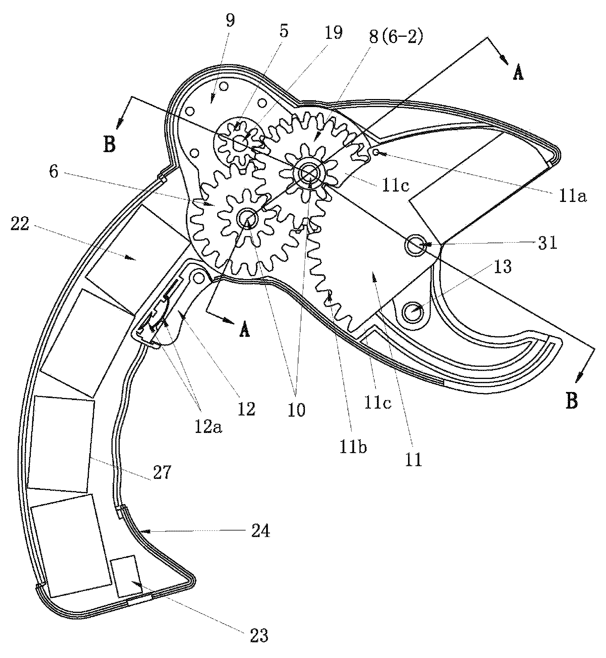
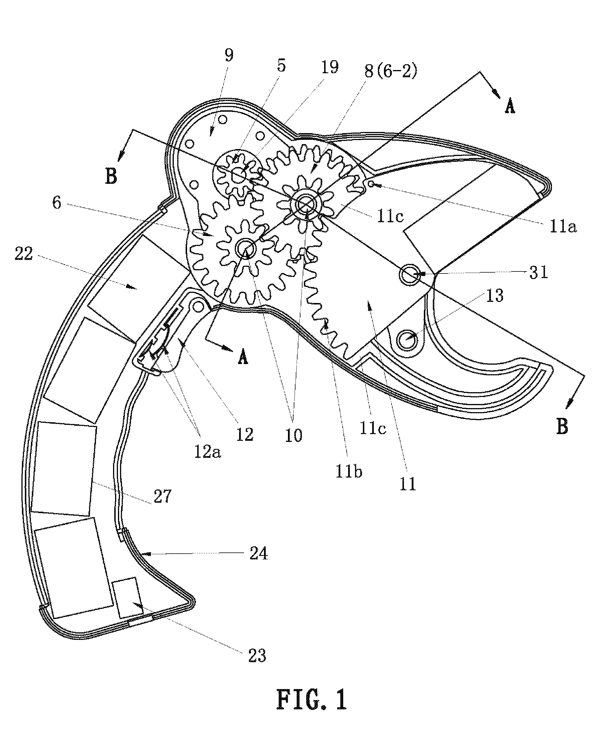
[0046]As shown in FIGS. 1 to 6, a plastic pipe cutting tool comprises a housing body with a handle, the housing body is divided into left housing body 1 and right housing body 24, which are combined and fastened so as to form the housing body. The upper portion of the housing body is jaw-shaped, the middle-upper portion of housing body is an inflated assembly chamber 25 for assembling primary components including a motor 21, a variable speed gearing mechanism, a blade holder 28 and so on, and the middle-lower portion of the housing body is substantially an arc handle 26, in which a battery chamber 27 for containing plurality of battery as power supply 22 is disposed, the end of the handle 26 is provided with a charging socket 23 forming a charging circuit with connecting wire, the handle 26 is assembled in the front side with a switch 12, coordinating operation buttons and a metal contact piece pair 12a therein, with association of operation button 12, a loop circuit is composed of ...

example 2

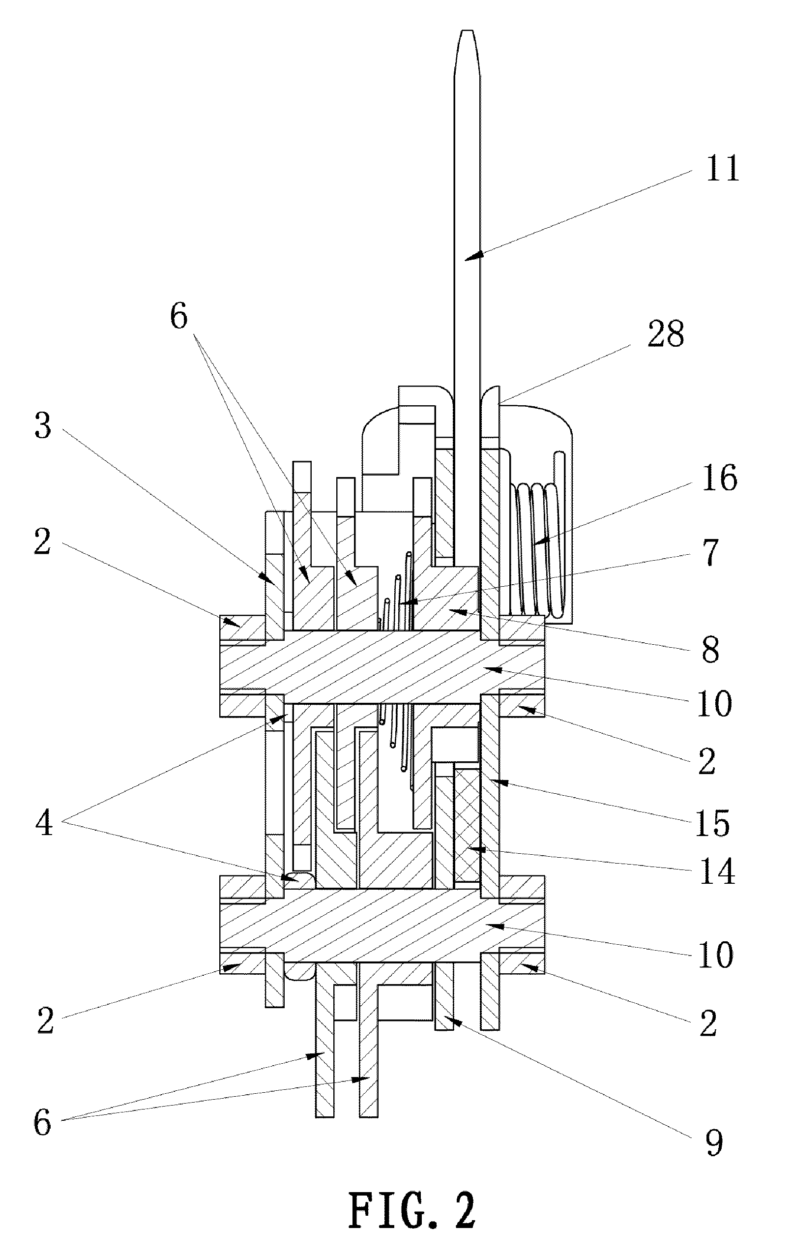
[0053]A plastic pipe cutting tool comprises a housing body with a handle, a blade holder mounted on the housing body and a rotatable blade associated with the blade holder to form a cutting opening, and said housing body is provided with a motor which is drivable connected with said blade via a variable speed gearing mechanism, and is further provided with a power supply which is electrically connected with the motor by switch to form a loop circuit, wherein said variable speed gearing mechanism further comprises a variable speed frame mounted to the housing body, the variable speed frame is assembled with rotary worm 30 that is connected by a coupling directly or indirectly with the output shaft of motor, the worm 30 is also engaged with partial gear 11b on the tail portion of blade 11 where provides with space 11c on the front and rear portions for preventing from transmission, as shown in FIG. 7. The others are same as the Example 1 except of a clutch mechanism.

example 3

[0054]As shown in FIGS. 11-12, a plastic pipe cutting tool comprises a housing body with a handle, a blade holder mounted on the housing body and a rotatable blade associated with the blade holder to form a cutting opening, and said housing body is provided with a motor which is drivable connected with said blade via a variable speed gearing mechanism, and is further provided with a power supply which is electrically connected with the motor by switch to form a loop circuit, wherein a partial gear 11b is molded at the rear portion of blade 11, and a space 11c is disposed between the upper portion of the partial gear 11b and the upper edge of the blade 11, and a transmission gear 32 as a power section is further provided to engage with the partial gear 11b of the blade, and to connect directly or indirectly with the motor 21.


PUM

PropertyMeasurementUnit
lengthaaaaaaaaaa
diameteraaaaaaaaaa
speedaaaaaaaaaa

Abstract

The present invention relates to a plastic pipe cutting tool comprising a housing body with handle, a blade holder mounted on the housing body and a rotatable blade associated with the blade holder to form a cutting opening, is characterized in that said housing body is provided with a motor which is drivable connected with said blade, and is further provided with a power supply which is electrically connected with the motor by switch to form a loop circuit. The plastic pipe cutting tool according to the present invention is driven by electric and can decrease labor intensity, and is light and easy-carried.

Description

CROSS REFERENCE TO THE RELATED PATENT APPLICATION[0001]The present application claims the priority of the Chinese patent applications No. 200820122180.0 filed on Jul. 25, 2008, No. 200820167079.7 filed on Oct. 29, 2008, No. 200820167080.X filed on Oct. 29, 2008, which applications are incorporated herein by reference.TECHNICAL FIELD[0002]The present invention for utility model relates to a cutting tool, particularly used for cutting PVC plastic pipe, aluminum-plastic compound pipe or the like.TECHNICAL BACKGROUND[0003]As progress of science and technology, various kinds of plastic pipe and aluminum-plastic compound pipe are applied in the occasions where people live and work. During the application of PVC plastic pipe, a cutting knife is usually used for cutting plastic pipes so as to make it into the length required, thus many scientists devote to develop novel cutting knife or cutter suitable for cutting plastic pipe.[0004]The Chinese patent No. 200720109332.9 disclosed a “rotary ...

Claims


Application Information

Patent Timeline
Patent Type & Authority Patents(United States)
IPC IPC(8): B23D21/10B26D3/16
CPCB26B15/00B26D3/169
Inventor HUANG, ZHONGHUA
Owner NINGBO JF TOOLS INDAL
Why Eureka
Try Eureka