
Method and apparatus for the non-destructive measurement of the compressive strength of a solid

a non-destructive measurement and compressive strength technology, applied in the direction of measuring devices, scientific instruments, instruments, etc., can solve the problems of error in the bound velocity, and achieve the effect of increasing the accuracy of the instrument, reducing the sensitivity of the device, and reducing the time span for gravity to a

Active Publication Date: 2012-09-11
BRANDESTINI MARCO
View PDF23 Cites 12 Cited by
  • Summary
  • Abstract
  • Description
  • Claims
  • Application Information

AI Technical Summary

Benefits of technology

The solution provides more accurate and reliable compressive strength measurements, reducing errors and increasing the instrument's sensitivity, while being easier to calibrate and maintain, with a user-friendly display and robustness against environmental factors like dust and moisture.

Problems solved by technology

In addition, it is based on the understanding that a single measurement of the rebound velocity will suffer from errors due to the strong mechanical disturbances the instrument is subjected to during rebound.

Method used


Image

  • Method and apparatus for the non-destructive measurement of the compressive strength of a solid
  • Method and apparatus for the non-destructive measurement of the compressive strength of a solid
  • Method and apparatus for the non-destructive measurement of the compressive strength of a solid

Examples


Embodiment Construction

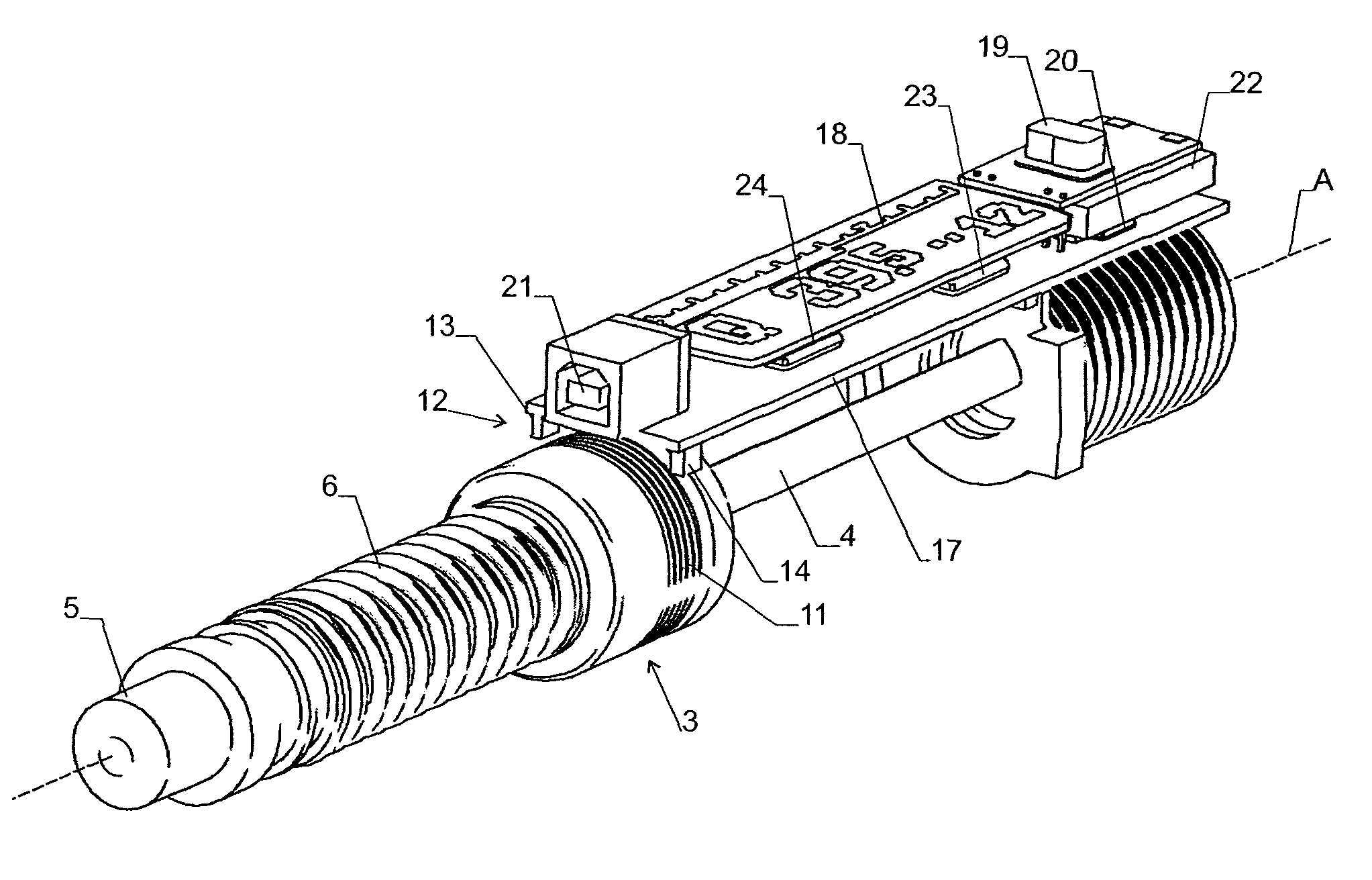
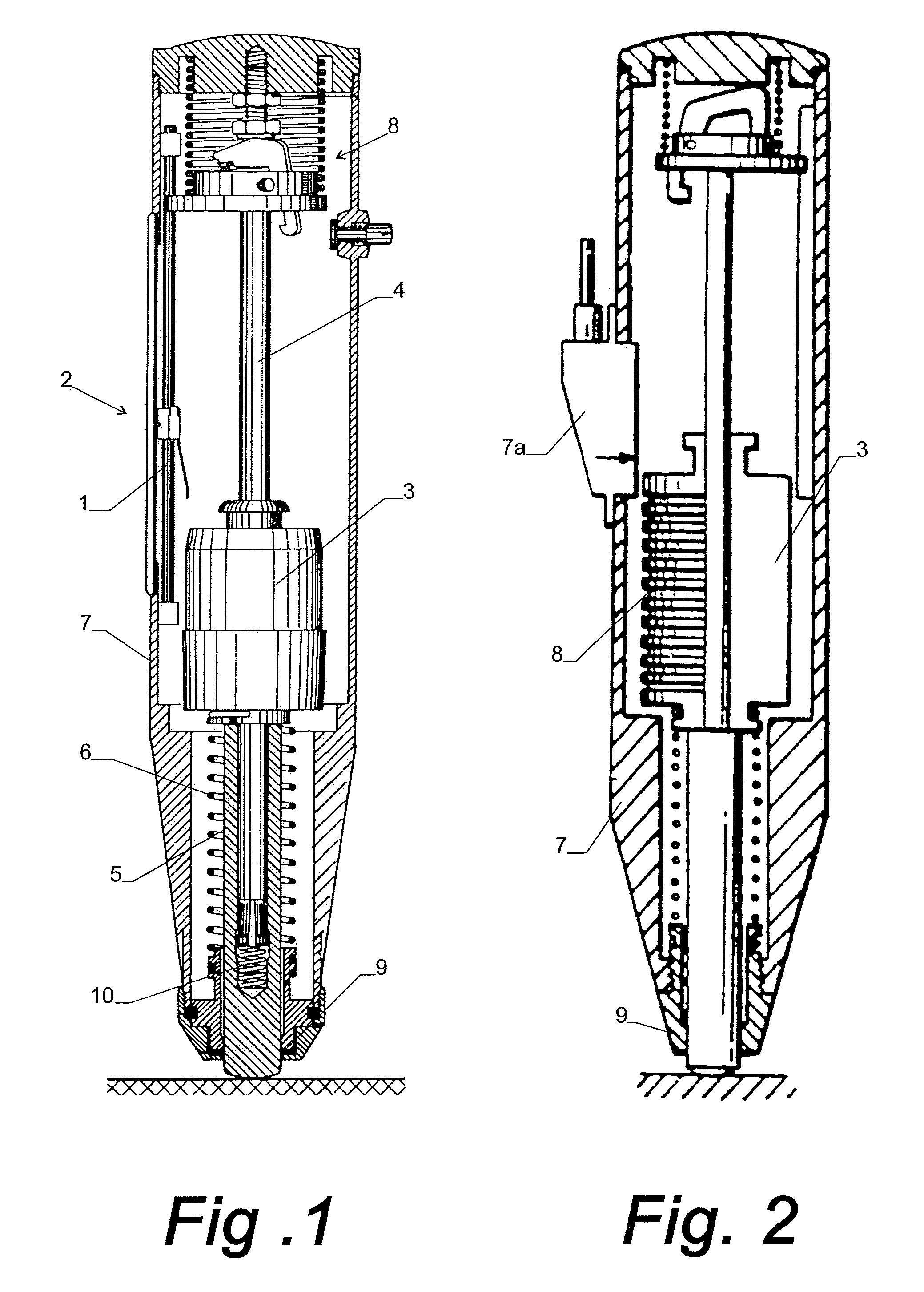
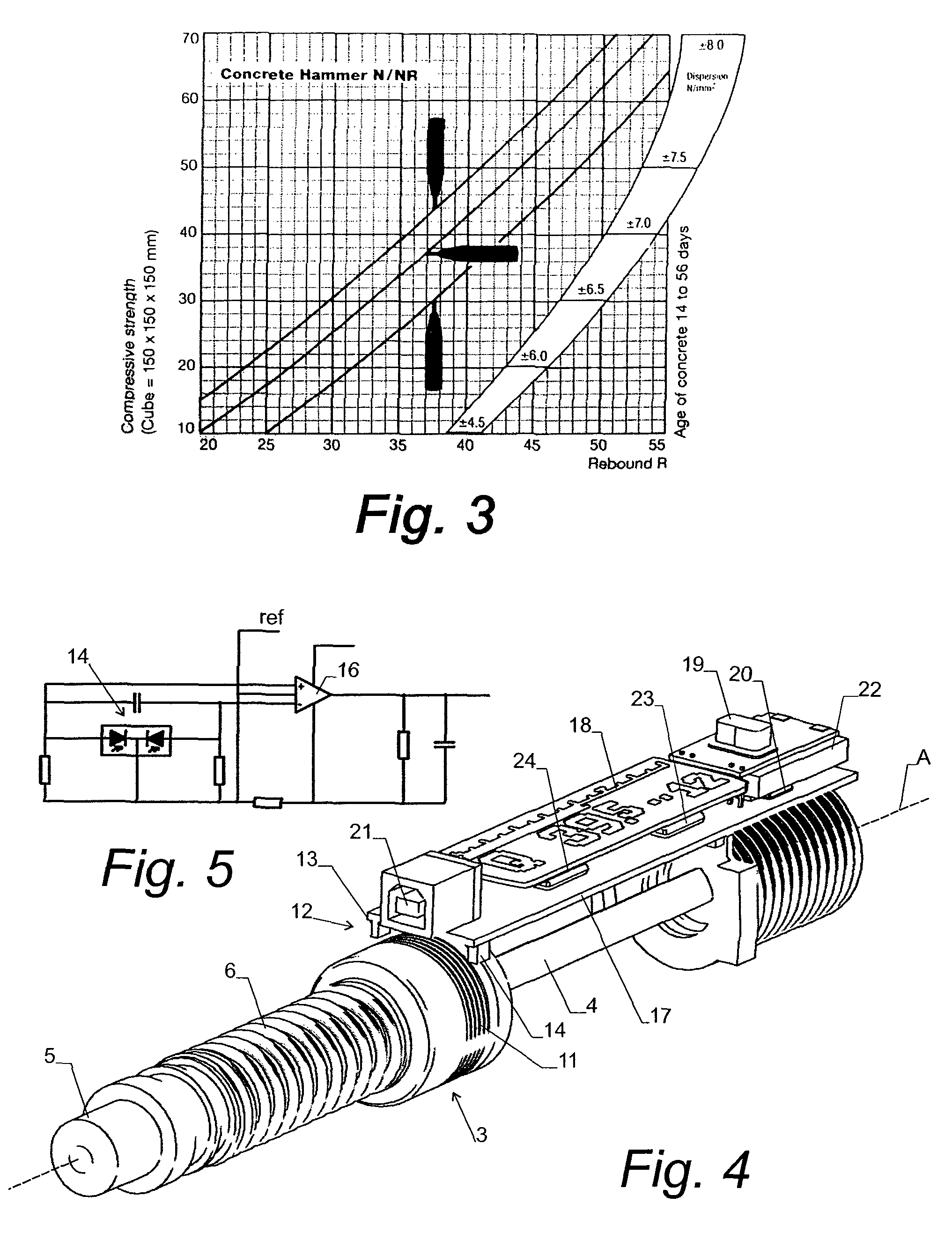
[0042]FIG. 4 shows the relevant parts of an advantageous embodiment of the device at the time of impact. The housing has been omitted for simplicity (FIG. 6 shows the complete hammer unit). We note the mallet 3, which travels along an axis A on a guide rod 4 and impinges on the plunger 5 drawn by the impact spring 6, with impact spring 6 acting as a drive mechanism for driving mallet 3 against plunger 5. These parts are virtually identical to the classic implementation as e.g. described in U.S. Pat. No. 5,176,026. However, the mass of the mallet 3 is now reduced to match the mass of the plunger. This is to ensure that the energy of the mallet is transferred to the plunger in one single blow, when it travels toward the plunger and from the plunger to the mallet upon return. In the classic unit there are multiple contacts of a random number, whereby a part of the energy is lost. Further advantages of this design have been described above.

[0043]Note that the impact spring 6 is the same...


PUM

PropertyMeasurementUnit
areasaaaaaaaaaa
compressive strengthsaaaaaaaaaa
compressive strengthaaaaaaaaaa

Abstract

An apparatus and a method are described that determine the compressive strength of a solid by rebound. The method and apparatus have a reduced sensitivity to error sources, i.e. gravity, internal friction and operator interference (unsteady holding of the instrument). The improvements are achieved by contactless measuring of the quotient of rebound to inbound velocity recorded immediately before and after the impact. Matching the mass of the mallet (3) to the plunger (5) yields higher efficiency, less angular variation of the impact energy and lighter weight. Added benefits of the invention are: Extended range of measurement and simplified mechanical adjustments, calibration and maintenance.

Description

TECHNICAL FIELD[0001]The invention relates to a method and apparatus for the non-destructive measurement of the compressive strength of a solid, in particular of concrete.BACKGROUND ART[0002]Since the fifties methods have been in use to assess the compressive strength of concrete using an apparatus with a defined tip to impact upon the surface to be tested.[0003]The best known method is the so-called Schmidt hammer that generates a defined impact energy by extending a spring and letting it drive a mallet. This mallet in turn hits upon a plunger that transfers the impact to the surface to be tested.[0004]Upon impact the concrete is compressed and part of the energy is absorbed by plastic deformation. The remaining energy is returned and causes the plunger to rebound. The rebound is then transferred back to the mallet. The mallet then compresses the spring until the kinetic energy of the mallet is fully transferred into deformation energy of the spring. The point of this maximum compr...

Claims


Application Information

Patent Timeline
Patent Type & Authority Patents(United States)
IPC IPC(8): G01N3/00
CPCG01N3/307G01N3/52G01N2203/0019G01N33/383
Inventor BRANDESTINI, MARCO
Owner BRANDESTINI MARCO
Learn More