Method for repairing a damaged composite component having fibre optics

a composite component and fibre optic technology, applied in the direction of process and machine control, mechanical control devices, instruments, etc., can solve the problems of mechanical damage of such composite fibre components, and the risk of glass fibres integrated therein being damaged, in particular severed

Active Publication Date: 2012-09-11
AIRBUS OPERATIONS GMBH
View PDF11 Cites 0 Cited by
  • Summary
  • Abstract
  • Description
  • Claims
  • Application Information

AI Technical Summary

Benefits of technology

[0008]The object of the invention is therefore to provide a method and a device whereby a repair of damaged composite fibre components with integrated fibre optics is possible.
[0010]This also makes it possible for the first time, manually and at relatively little cost, even in “in-field” operation, to repair damage to a composite fire component with integrated fibre optics resulting in at least partial severing of the fibre optic. The fibre optic integrated in the composite fibre component, which generally comprises at least one discrete glass fibre with a diameter of between 50 μm and 150 μm, runs together with the carbon fibres generally used as a reinforcing fibre arrangement, inside the resin matrix of the composite material. The fibre optic can also be woven, twisted or threaded with the reinforcing fibre optic. The glass fibre or fibre optic (so-called Fibre Bragg Grid Sensors (“FGBS”)) exhibits, at defined distances, density distances which represent a grid. In the case of a slight extension of the glass fibre by forces acting from outside on the CFRP component, the grid distance between these density zones varies, as a result of which the frequency of light introduced into the fibre also varies. These frequency displacements can be evaluated by measurement for the qualitative recording of a variation in the length of the CFRP component.
[0018]A further advantageous embodiment of the method provides for the bridging fibre optic to be formed preferably with optical fibres laid along the edge area. Because the repair fibre optic is laid on the peripheral, thickened edge area of the removed damaged area, the gluing area can also be monitored simultaneously and the integrity of the adhesion during operation can therefore be guaranteed. If necessary, additional sensors must be provided in the repair fibre optic if necessary. Alternatively it is possible to lay the repair fibre optic over the shortest distance directly through the removed area, which is generally formed by a straight line.
[0023]The bottom of the second container is preferably designed as a membrane that can be penetrated to create a “valve”. To facilitate the penetration process the pipe connected to the contact body is provided at the end with a dome or tip which pierces the membrane when the pipe is inserted in the second container, thereby making a connection between the second container and the contact body.
[0025]In order to control the degree of neutralisation the lye in the first container can be mixed with the optical pH indicator. Furthermore, the valve, in contrast to the (membrane) penetrating valve, is again displaceable so that the neutralisation can take place by way of a “titration”. In this case small defined volumes of the lye can be discharged into the second container and hence into the contact body by alternately opening and reclosing the valve for a short time, thus enabling the desired neutral pH value of approximately “7” to be set precisely to complete the exposing process of the fibre optic in the working area.
[0026]The contact body is formed with an acid resistant, elastic rubber material which is designed roughly in the shape of a bell. The lower peripheral edge of the contact body, which rests on a composite fibre component, has at least one elastic rubber lip. The spatial area of influence (working area) of the acid on the zone of the composite fibre component to be freed from the epoxy resin matrix for exposing the fibre optic is defined by the contact body and uncontrolled escape of acid beyond the actual working area is reliably prevented.

Problems solved by technology

Mechanical damage of such composite fibre components, which may be caused, for example, by impact from stones, bird strike or the like, has so far presented a major problem.
For example, if the composite component is damaged by impact from stones, there is also a risk that the glass fibres integrated therein will be damaged, in particular severed.

Method used


Image

  • Method for repairing a damaged composite component having fibre optics
  • Method for repairing a damaged composite component having fibre optics
  • Method for repairing a damaged composite component having fibre optics

Examples


Embodiment Construction

[0035]In the drawing the same structural elements are denoted by the same reference numbers.

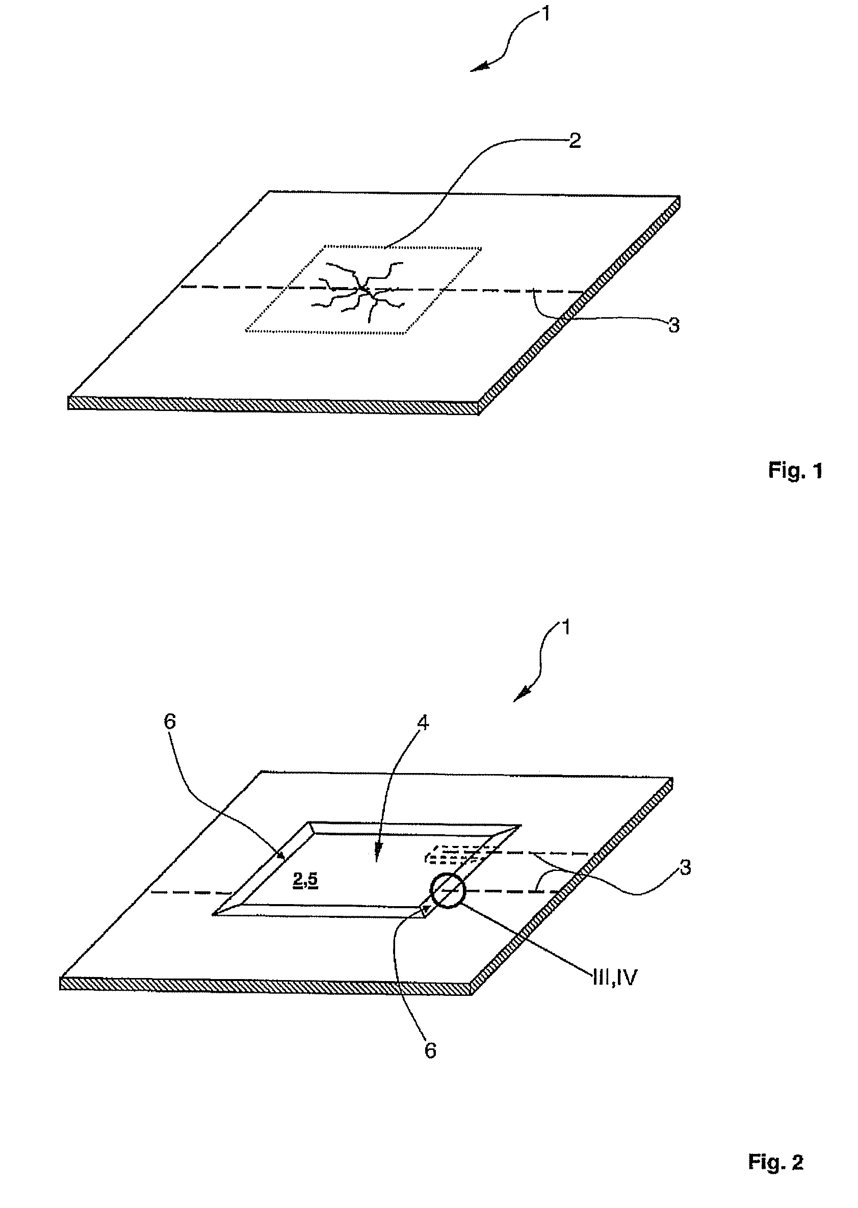
[0036]FIG. 1 shows a composite fibre component 1 of an aircraft with a damaged area 2, which has a multiplicity of cracks. The damage in composite fibre component 1 may, for example, have been caused by the impact of foreign bodies (so-called “impact”). The composite fibre component is formed in a known manner with a carbon fibre reinforced settable epoxy resin.

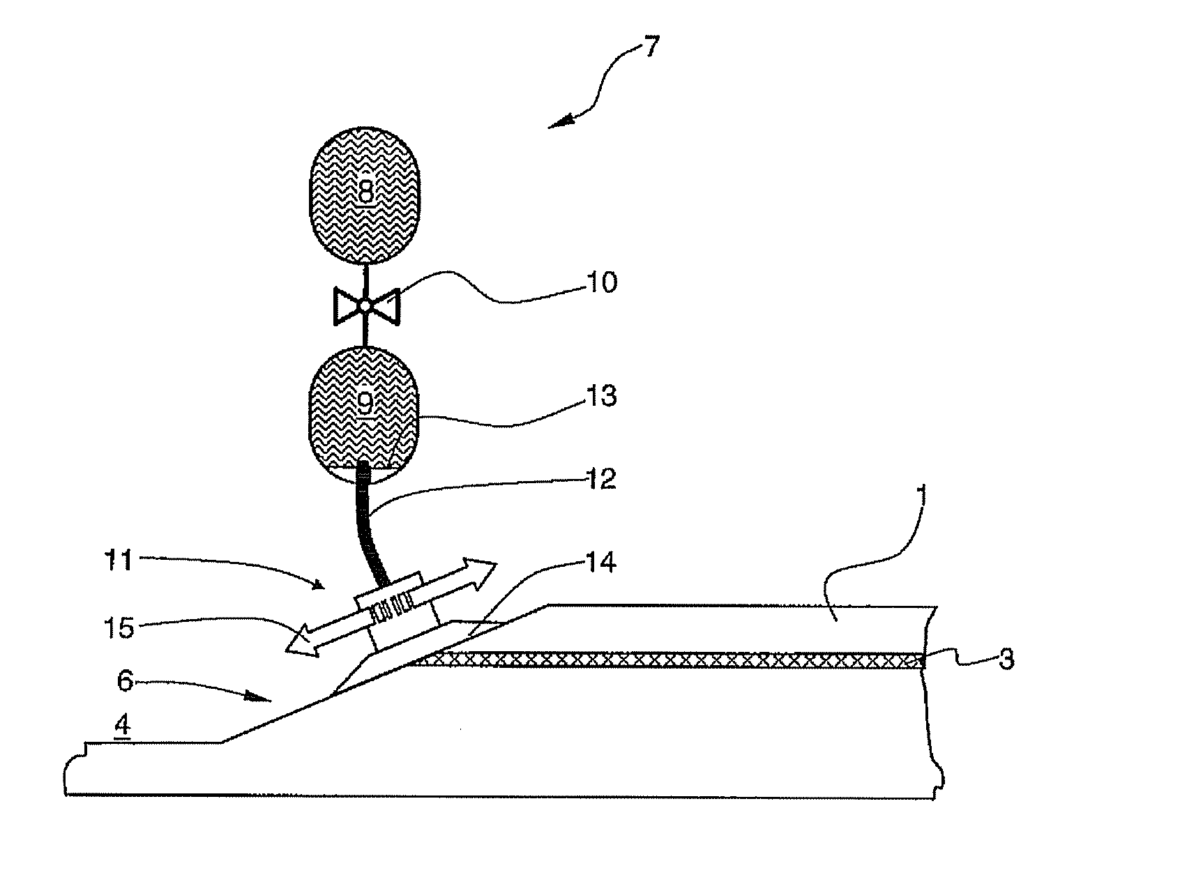
[0037]A fibre optic 3 is embedded or integrated in composite fibre component 1. Fibre optic 3 preferably comprises at least one glass fibre with a diameter of less than 100 μm. Fibre optic 3 serves, for example, to record mechanical loads and result performances of composite fibre component 1 and / or for the detection of crack formation resulting from fatigue phenomena. In addition a multiplicity of control information can be transmitted reliably inside the aircraft with the fibre optic.

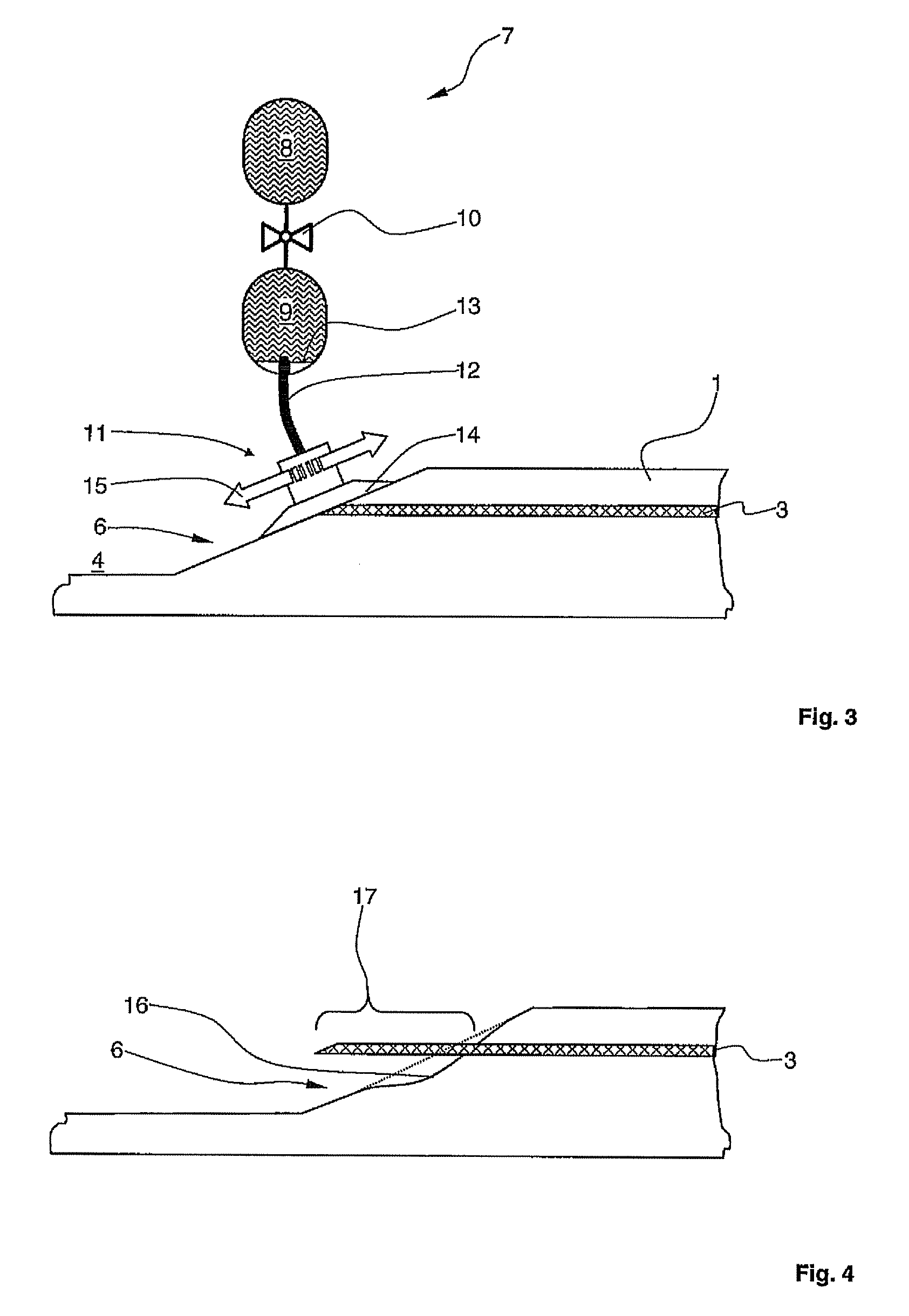
[0038]In a first method step damaged area 2 is pre...


PUM

PropertyMeasurementUnit
angle of inclinationaaaaaaaaaa
diameteraaaaaaaaaa
diameteraaaaaaaaaa

Abstract

The invention is directed to a method for repairing a damaged composite fiber component of an aircraft having at least one integrated fiber optic, the damaged area including both a damaged composite structure and a damaged optical fiber, comprising mechanically removing material from the damaged area, to form a removed area, exposing ends of the damaged composite fiber component in an edge area of the removed area, splicing-in a bridging fiber optic portion for restoring an optical connection, laying the bridging fiber optic along an edge area of the removed area, and pressing and gluing-in a repair patch into the removed area.

Description

CROSS-REFERENCE TO RELATED APPLICATIONS[0001]This application is a continuation of PCT International Application No. PCT / EP2008 / 058249 filed Jun. 27, 2008, which claims the benefit of U.S. Provisional Application No. 60 / 937,926, filed Jun. 29, 2007 and German Patent Application No. 10 2007 030 025.7, filed Jun. 29, 2007, the entire disclosures of which are herein incorporated by reference.FIELD OF THE INVENTION[0002]The invention relates to a method, in particular for repairing a damaged area of a composite fibre component of an aircraft, the composite fibre component having at least one integrated fibre optic.[0003]The invention also relates to a device for exposing a fibre optic integrated in a composite fibre component.[0004]DE 101 02 853 B4 discloses a laser protected, selective material removal process for composite fibre plastics, and WO 2007 / 003880A discloses a method for repairing damaged areas of composite fibre materials of an aircraft.[0005]In modern aircraft manufacture ...

Claims


Application Information

Patent Timeline
Patent Type & Authority Patents(United States)
IPC IPC(8): G02B6/255B32B43/00B44C1/22
CPCB29C73/10B29C73/26B29C2073/262B29C2073/264
Inventor WEISSER, ALEXANDER
Owner AIRBUS OPERATIONS GMBH
Why Eureka
Try Eureka