
Nth-order arbitrary-phase-shift sinusoidal oscillator structure and analytical synthesis method of making the same

a sinusoidal oscillator and phase shift technology, applied in the direction of oscillator generators, electrical equipment, etc., can solve the problems that none of the analytical synthesis methods have been applied to the design of oscillator structures, and achieve the effects of reducing total parasitics, power consumption, chip areas, and nois

Inactive Publication Date: 2012-09-11
CHUNG YUAN CHRISTIAN UNIVERSITY
View PDF2 Cites 15 Cited by
  • Summary
  • Abstract
  • Description
  • Claims
  • Application Information

AI Technical Summary

Benefits of technology

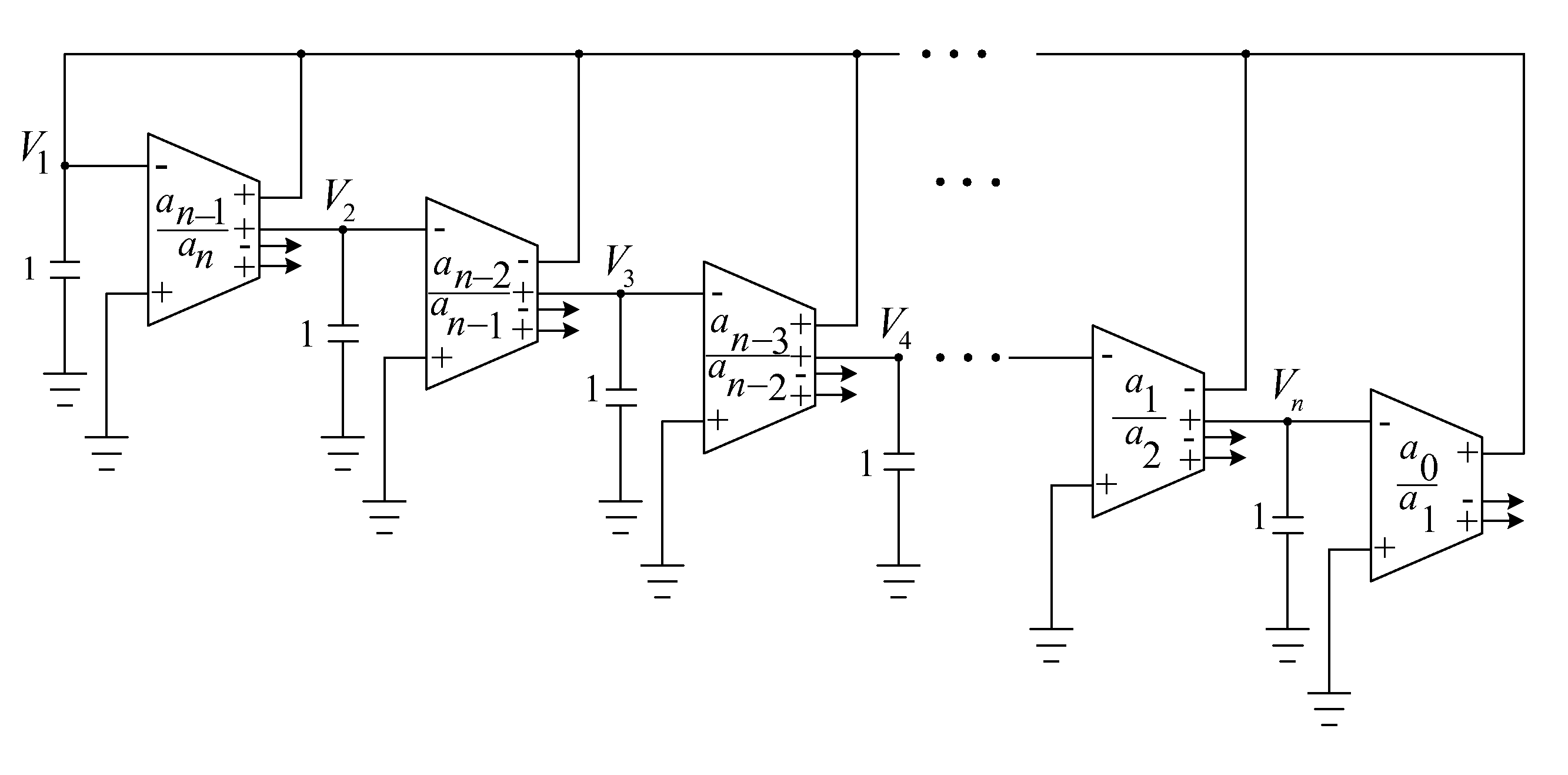
"The patent text describes a new method for designing oscillator circuits that meet three important criteria simultaneously: grounded capacitors to absorb equivalent shunt capacitances, single-ended-output operational transconductance amplifiers to reduce feed-through effects, and a minimum number of active and passive components to reduce parasitics, power consumption, and noise. The method is applicable to any number of oscillators and can be easily followed by readers. The text also describes the synthesis of an nth-order any-phase-shift sinusoidal oscillator structure using a new method that simplifies the process of deriving the transfer function and reduces the deviation of the phase shifts and frequency of oscillation. The non-ideal factors introduced by the OTA and parasitic capacitances are compensated to improve the accuracy of the phase shifts and frequency. The method can be easily implemented and verified using H-Spice simulations."

Problems solved by technology

None of the analytical synthesis methods has been applied to the design of oscillator structures.

Method used


Image

  • Nth-order arbitrary-phase-shift sinusoidal oscillator structure and analytical synthesis method of making the same
  • Nth-order arbitrary-phase-shift sinusoidal oscillator structure and analytical synthesis method of making the same
  • Nth-order arbitrary-phase-shift sinusoidal oscillator structure and analytical synthesis method of making the same

Examples


case ii (

Third-Order One with Two 120° Phase Shifts):

[0220]Let the W / L be (i) 5μ / 0.5μ and 5μ / 0.5μ, (ii) 20μ / 0.5μ and 20μ / 0.5μ, (iii) 20μ / 0.5μ and 20μ / 0.5μ, (iv) 5μ / 2.5μ and 10μ / 2.5μ, and (v) 5μ / 2.5μ and 10μ / 2.5μ, for NMOS and PMOS transistors, respectively, in the (i) OTA1, (ii) OTA2, (iii) OTA3, (iv) OTA4, and (v) OTA5. The component values are given by C1=20 pF, C2=10 pF, C3=10 pF, and g1=24.184 μS (Ib=2.042 μA), g2=g3=145.039 μS (Ib=12.638 μA), g4=g5=36.276 μS (Ib=5.465 μA). The oscillation waveforms of the node voltages, V1, V2, and V3, are shown in FIG. 34, whose frequency spectrums are shown in FIG. 35. The THDs of V1, V2, and V3, are 0.6119%, 1.8691%, and 0.7293%, respectively. The phase of V1 lags behind V2 by 121.141° with error 0.951% and the phase of V2 lags behind V3 by 121.378° with error 1.148%. The simulation frequency is 938.262 kHz with error 6.174% compared to the theoretical 1 MHz.

Case III (Third-Order One with Two 60° Phase Shifts):

[0221]We give the W / L=(i) 5μ / 1μ and 10μ / ...


PUM


Abstract

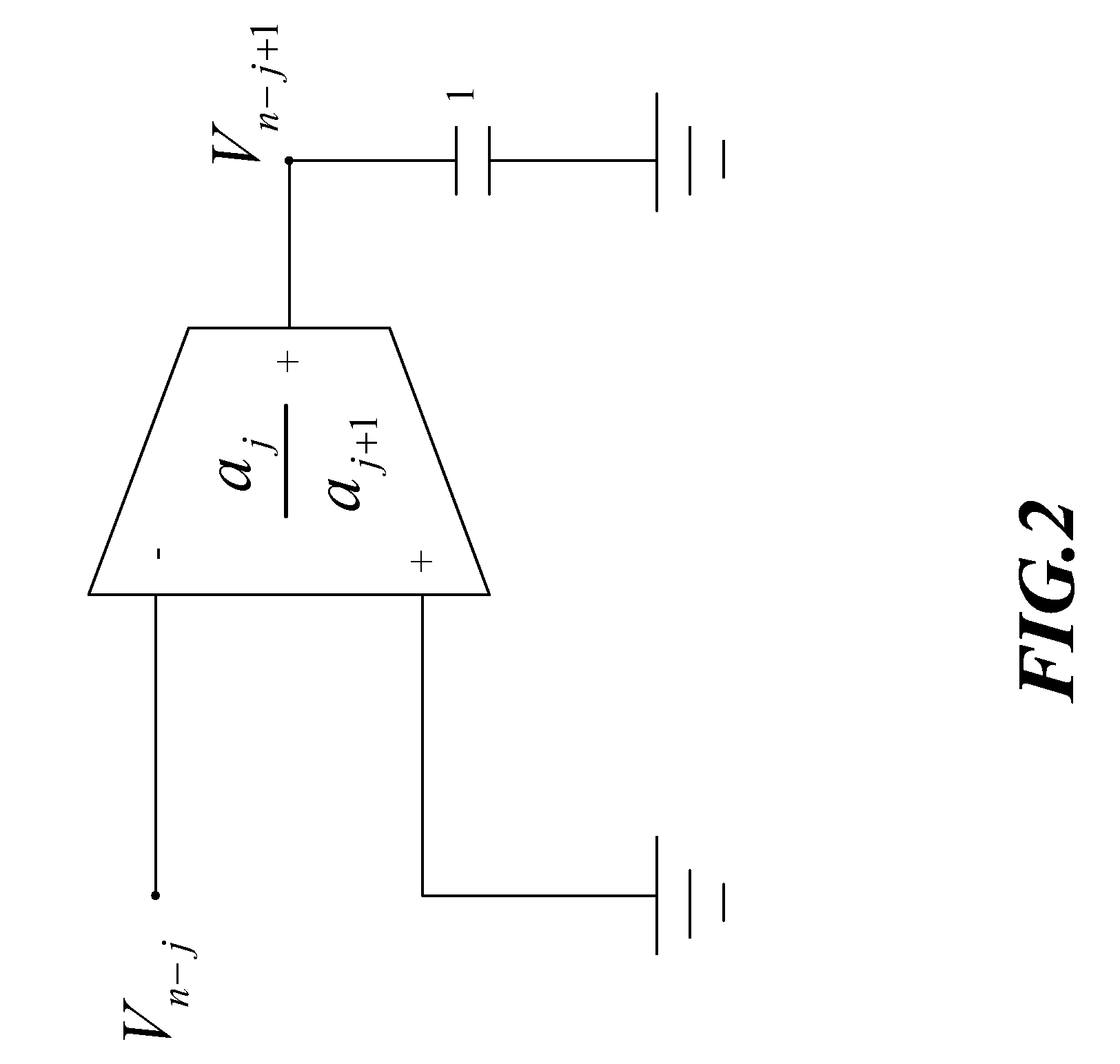
Nth-order voltage- and current-mode arbitrary phase shift oscillator structures are synthesized using n operational trans-conductance amplifiers (OTAs) or second-generation current controlled conveyors (CCCIIs) and n grounded capacitors. Linking up the I / O characteristics of the OTA and the CCCII and the reactance of grounded capacitor, the step of synthesis is first based on the algebraic analysis to oscillatory characteristic equations, resulting in a quadrature oscillator structure. Secondly, instead of the quadrature characteristic, to control each output signal with one another by a desired phase difference > or <90°, selectively superposing any of two fundamental OTA / CCCII-C sub-circuitries benefits the transformation of quadrature to arbitrary-phase-shift characteristic for the sinusoidal oscillator structure. Furthermore, several compensation schemes are presented for reducing the output parameter deviation due to the non-ideal effects.

Description

CROSS-REFERENCE[0001]This application claims priority from U.S. Provisional Patent Application No. 61 / 170,809, filed on Apr. 20, 2009.FIELD OF THE INVENTION[0002]The present invention relates to nth-order any-phase-shift sinusoidal oscillator structure and more specifically using analytical synthesis method for the synthesis of the voltage-mode and current-mode nth-order any-phase-shift sinusoidal oscillator structure.DESCRIPTION OF THE PRIOR ART[0003]Quadrature or multiphase sinusoidal oscillators have been considerably attended by analog circuit designers especially for recent several years. For instance, the availability of I / Q local oscillator (LO) references is essential for the monolithic implementation of direct-conversion receivers [1]. The phase-locked loop (PLL) operates as an edge-combining type fractional-N frequency synthesizer / multiplier using multiphase clock signals from a ring-type voltage-controlled oscillator (VCO) [2-3]. Moreover, multiphase sampling clock can be...

Claims


Application Information

Patent Timeline
Patent Type & Authority Patents(United States)
IPC IPC(8): H03B5/20
CPCH03B27/00
Inventor CHANG, CHUN-MINGTU, SHU-HUI
Owner CHUNG YUAN CHRISTIAN UNIVERSITY
Learn More