
Illuminating apparatus and display apparatus

a technology of illumination apparatus and display apparatus, which is applied in the direction of non-linear optics, static indicating devices, instruments, etc., can solve the problems of limited number of dividing regions (the smallest size of the region which is made dark), physical limitations and economic limitations, and it is difficult to divide the screen in a two-dimensional matrix of rows and columns. , to achieve the effect of reducing light intensity locally, improving transmittance, and high contrast ratio

Active Publication Date: 2012-09-11
SATURN LICENSING LLC
View PDF17 Cites 0 Cited by
  • Summary
  • Abstract
  • Description
  • Claims
  • Application Information

AI Technical Summary

Benefits of technology

The present invention provides an illuminating apparatus and a display apparatus that can locally reduce light intensity without depending on the configuration of the light source element itself. This is achieved by regulating the transmission amount of light generated from the light source by a liquid crystal light control panel, which allows for a controlled reduction of light intensity in specific regions without the need for additional light source elements or increased division number. The invention also optimizes the polarization degree of the polarizers in the liquid crystal light control panel to improve transmission light amount ratio and suppress transmission light amount ratio, resulting in improved contrast ratio and reduced insertion loss.

Problems solved by technology

However, in designing, the maximum number of dividing the region (the smallest size of the region which is made dark) is limited in reality due to physical limitation of the number of light source elements which is used and physical limitation of arrangement of the light source elements.
As described above, in the case of obtaining the larger division number, the physical limitation and economic limitation arise.
Consequently, in a configuration of disposing about 20 line light sources such as CCFLs, it is difficult to divide the screen in a two-dimensional matrix of rows and columns.
In a combination with a video signal having a two-dimensional space frequency in the vertical and horizontal directions, the effect of the partial-drive-type is not easily produced.
It is therefore improper to use line light sources.

Method used


Image

  • Illuminating apparatus and display apparatus
  • Illuminating apparatus and display apparatus
  • Illuminating apparatus and display apparatus

Examples


first embodiment

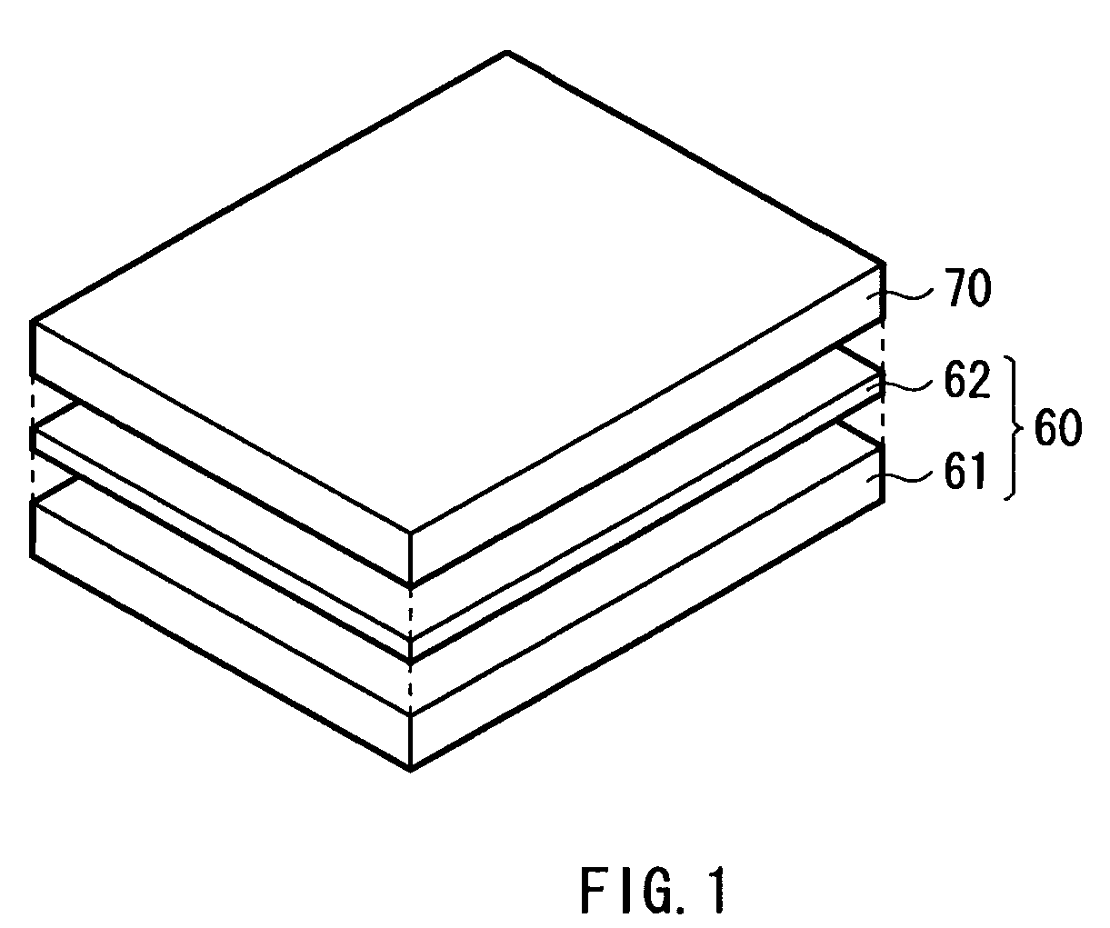
[0039]FIG. 1 shows a configuration example of a display apparatus in a first embodiment of the present invention. The display apparatus is a liquid crystal display apparatus of a transmission type and has a backlight 60 as an illuminating apparatus and a liquid crystal display panel 70. The liquid crystal display panel 70 is a display part for displaying a video image based on an input video signal Vin using illumination light from the backlight 60 as display light. The backlight 60 has a light source unit 61 and a diffusion part 62. The diffusion part 62 is obtained by, for example, stacking a plurality of plate-shaped optical members such as diffusers having uniform diffusion degree or optical sheets for improving general light intensity.

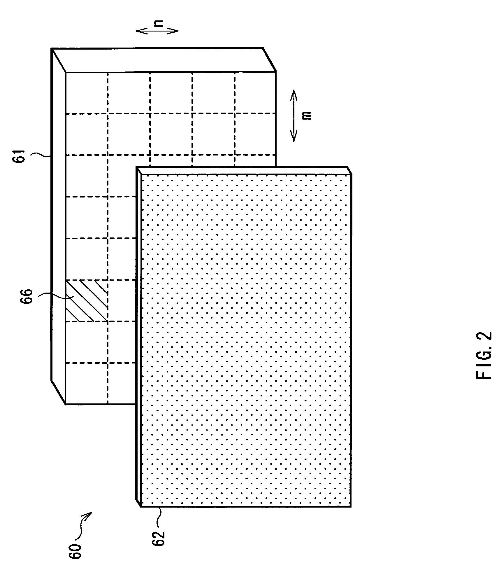
[0040]The light source unit 61 in the backlight 60 has, as shown in FIG. 2, a plurality of partial light emission regions 66 obtained by dividing a light emission area in the in-plane direction (“n” in the vertical direction x “m” in the horizonta...

second embodiment

[0075]A second embodiment of the present invention will now be described. The same reference numerals are designated to the substantially same components as those of the first embodiment and their description will not be repeated.

[0076]In the first embodiment, the case of using stick-shaped line light sources such as CCFLs as the light source 1 has been described. As the light source 1, point light sources may be used. For example, as shown in FIG. 22, as the light source 1, a combination of a red LED 1R for emitting red light, a green LED 1G for emitting green light, and a blue LED 1B for emitting blue light may be disposed in each of the partial light emission regions 66 in the light source unit 61. In this case, by additive color mixing of those colors, white light is obtained. At least one LED of each color is disposed in each of the partial light emission regions 66.

Other Embodiments

[0077]The present invention is not limited to the foregoing embodiments but other modifications ...


PUM

PropertyMeasurementUnit
drive frequenciesaaaaaaaaaa
drive frequencyaaaaaaaaaa
luminanceaaaaaaaaaa

Abstract

The present invention provides an illuminating apparatus locally reducing light intensity without depending on the configuration of a light source itself. An illuminating apparatus used as a backlight of a display apparatus having a liquid crystal display panel with a pair of first polarizers, including a light source and a liquid crystal light control panel. The liquid crystal light control panel has a pair of second polarizers and suppresses amount of transmission of light from the light source, thereby allows the light from the light source to have such a light intensity distribution along a plane that light intensity is locally reduced. The polarization degree in the second polarizers is optimized so that transmission light amount ratio of the second polarizers is lower than that of the first polarizers.

Description

[0001]The present application claims priority from Japanese Patent Application No. JP 2008-105768, filed in the Japanese Patent Office on Apr. 15, 2008, the entire content of which is incorporated herein by reference.BACKGROUND OF THE INVENTION[0002]1. Field of the Invention[0003]The present invention relates to an illuminating apparatus capable of varying a light intensity distribution in a plane and a display apparatus using the illuminating apparatus.[0004]2. Description of the Related Art[0005]For example, as a light source of a backlight of a liquid crystal display apparatus, a light source using a stick-shaped fluorescent tube such as CCFL (Cold Cathode Fluorescent Lamp), EEFL (External Electrodes Fluorescent Lamp), or HCFL (Hot Cathode Fluorescent Lamp) is conventionally known. A backlight using a stick-shaped ultraviolet lamp as a light source, converting ultraviolet light to visible light, using the visible light as illumination light is also proposed (refer to Japanese Une...

Claims


Application Information

Patent Timeline
Patent Type & Authority Patents(United States)
IPC IPC(8): G09G3/36G02F1/1347
CPCG02F1/133602G09G3/342G09G3/3426G09G3/3611G02F2001/133601G09G2300/023G09G2310/08G09G2320/0247G09G2320/0646G02F1/133601
Inventor FURUKAWA, NORIMASASHIMIZU, JUN
Owner SATURN LICENSING LLC
Learn More