Monitoring unit for a device for manipulating containers

a monitoring unit and container technology, applied in the direction of program control, total factory control, instruments, etc., can solve the problems of user carrying out a large number of unnecessary steps, laborious and time-consuming task of finding faults, etc., to improve the self-descriptiveness of the machine, improve the maintenance effect, and simplify the operation of the devi

Active Publication Date: 2012-09-11
KRONES AG
View PDF26 Cites 4 Cited by
  • Summary
  • Abstract
  • Description
  • Claims
  • Application Information

AI Technical Summary

Benefits of technology

[0004]The present invention is therefore based on the object of simplifying the operation of devices for manipulating containers, in particular in the beverage industry. In doing so, the various components and opportunities for improving the self-descriptiveness of the machine are intended to be improved by means of a test environment. In particular, user friendliness with regard to product changes to be carried out, with regard to fault visualisation and fault correction as well as with regard to maintenance is supposed to be improved.
[0013]The measures mentioned enhance the self-descriptiveness and the process reliability of the respective machine and thus also reduce the training needs for the machines and systems according to the invention. In addition, also the machine-specific training needs will be substantially reduced and intuitive operability will be enabled even for less well trained personnel.
[0014]The presentation data is preferable stored in the storage device in the form of vector graphics. A vector graphic is a two- or three-dimensional computer image made up of graphical primitives such as lines, circles and polygons. Unlike raster graphics, such vector graphics may be scaled and skewed in a continuously variable manner without any loss in quality, for example by means of homogenous coordinates. In principle, it would also be conceivable to store the respective graphics in the storage device in the form of images (such as bitmaps) or films. In this case, however, the storage capacity needs for the storage device would be very high. By using vector graphics, the storage capacity need may be considerably reduced. Moreover, on the basis of vector graphics having considerably lower storage capacity needs, it becomes possible to generate image sequences. For example, in the case of a fault on a component it is possible to indicate this component and also to indicate the steps to be taken to correct the fault.
[0015]Preferably, images of individual components of the machines, the device, the environment etc. are stored on the storage device in a simplified form. The basis used for generating this image data is preferably a full 3-D model. This model includes a geometrically exact picture of the component, which may be obtained for example from CAD documents. This full model requires, however, very high storage capacities and is therefore not practical for handling. Also, the user of the machine will get confused by such a full model due to the often dense clustering of details. Therefore, the images of the components are preferably stored in a simplified form, whilst for example any partial areas of the respective component, which are irrelevant to the user, are omitted. In this way, a storage space reduction of up to or even more than 99% may be achieved. Therefore it is also possible to provide the respective monitoring unit with relative low storage resources and it is in particular not necessary to provide expensive storage media such as for example CD ROM drives.
[0018]It is particularly preferred to store flow data in the storage device. By means of this flow data, which is basically a “script”, the image manipulation unit can, on the basis of a given condition signal and the presentation data stored on the storage device, generate a certain image sequence and output this via the display device. In this way, there is no need to deposit an image sequence for each conceivable condition of the device on the storage device, but just a schedule, i.e. the “script”. The image sequence shown will be generated anew by the image manipulation unit each time it is invoked. In this way, the storage capacity need of the storage device will be considerably reduced.
[0029]In a further preferred method, any instructions already carried out are saved. This provides a reliable way of checking at what stage of a product change or of checking a fault the user is.

Problems solved by technology

However, finding the fault often is a laborious and time-consuming task.
However, not in every case of converting from a first product type A to a second product type B, all the components involved will have to be changed, but often just a few steps are needed to convert the respective machine.
In this case it may thus occur that the user carries out a great number of unnecessary steps, since the machine has already been converted to some degree.

Method used


Image

  • Monitoring unit for a device for manipulating containers
  • Monitoring unit for a device for manipulating containers
  • Monitoring unit for a device for manipulating containers

Examples


Embodiment Construction

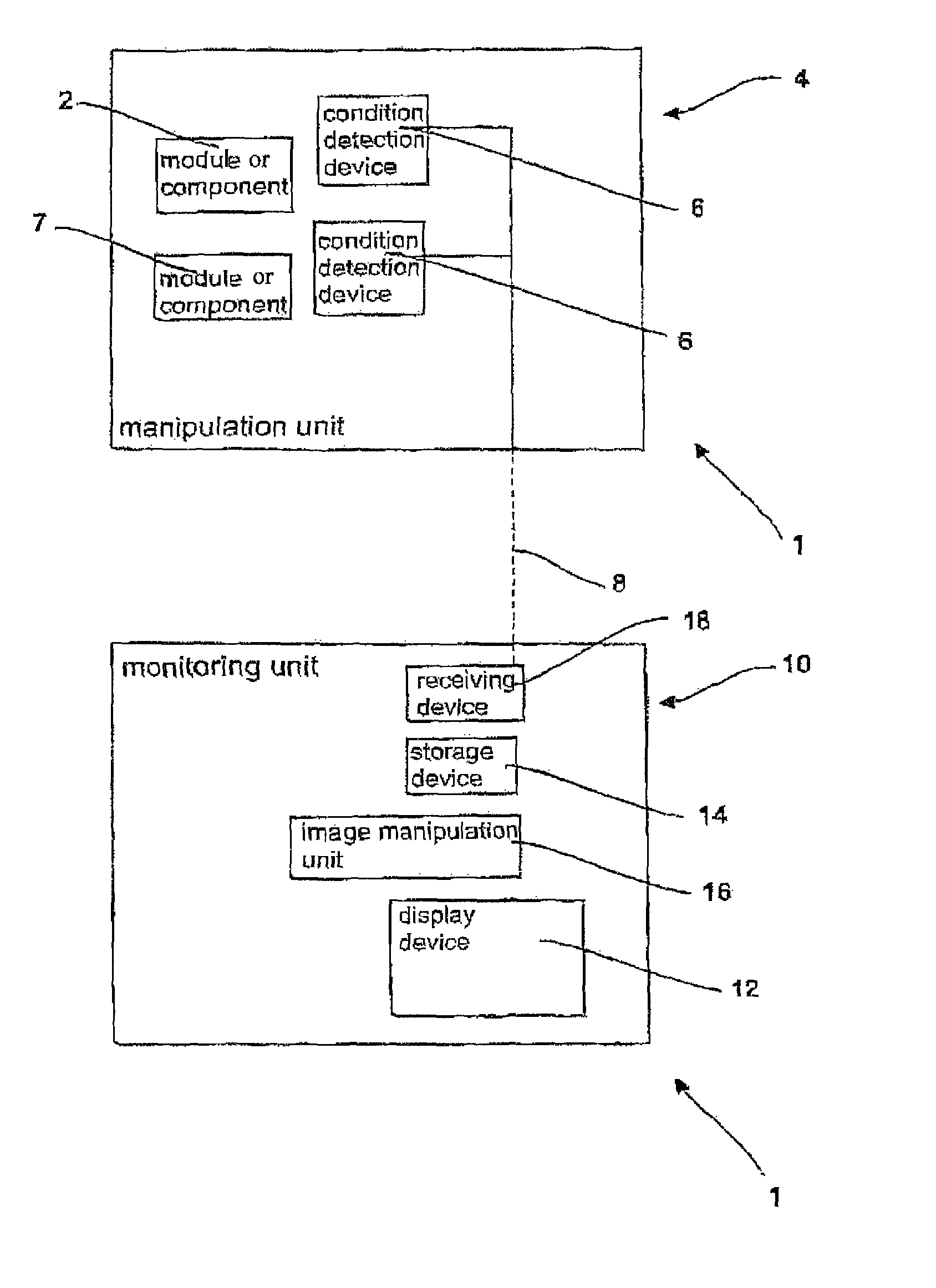
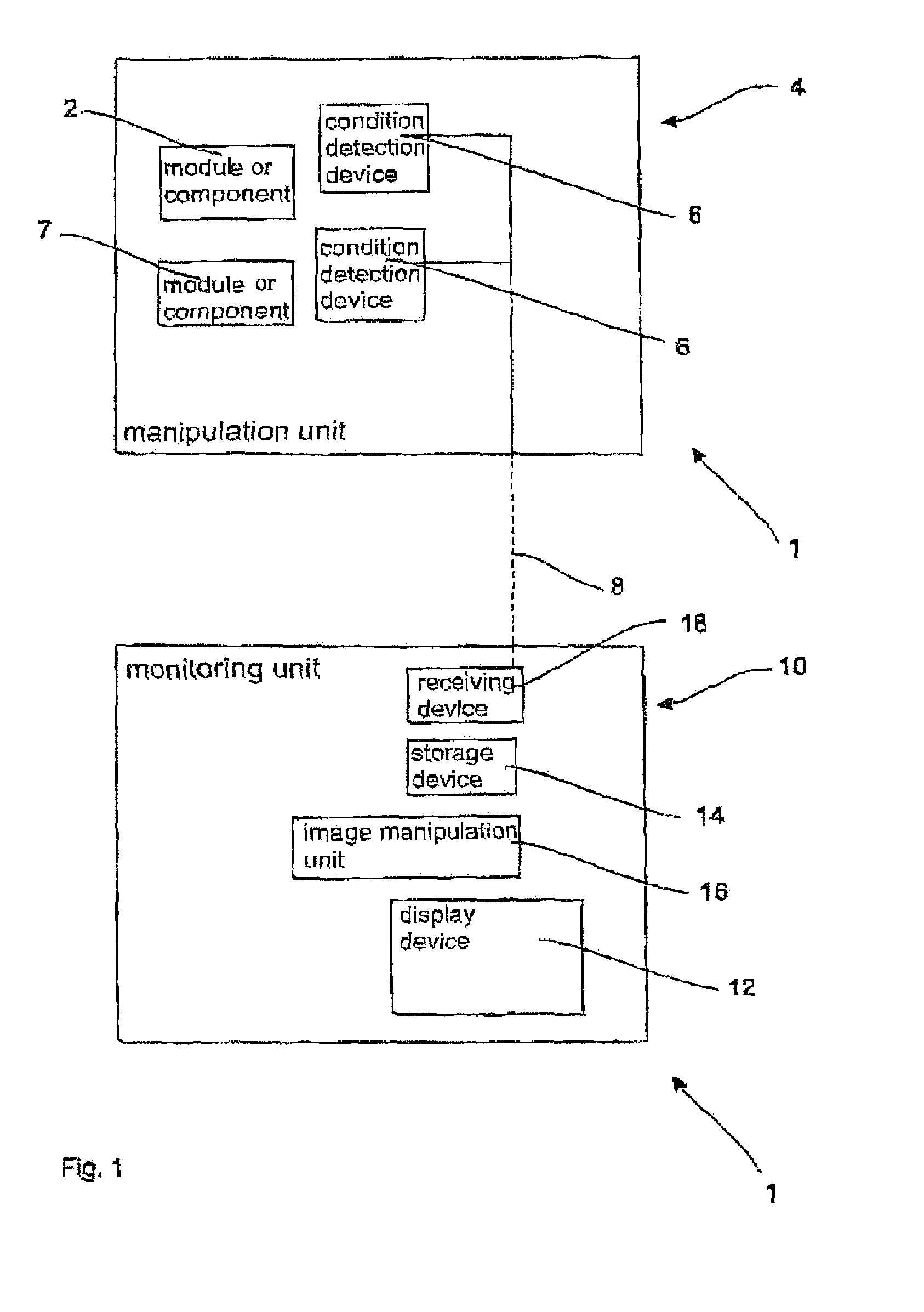
[0036]FIG. 1 shows a block diagram of a device 1 according to the invention for manipulating containers. This device 12 comprises a manipulation unit 4 for manipulating containers. This manipulating unit may, for example, be a labelling machine. The manipulation unit includes herein a plurality of individual modules or components, of which, however, only two components 2, 7 are shown. A component may e.g. also be a part not directly operatively connected to the machine, such as e.g. a conversion parts trolley with spare parts. Those two components each have a condition detection device 6 allocated to them, which detects an operating condition of the component or also of the manipulation unit 4 as a whole.

[0037]The condition detection devices 6 send out signals to the monitoring unit 10 via a communications link 8, which signals correspond to corresponding operating conditions of the manipulation unit 4 or the components 2, 7. The communications link 8 may be a cable connection, but ...


PUM


Abstract

A device for manipulating containers, comprising a manipulation unit manipulating the containers in a predetermined manner, this manipulation unit including at least one condition detection unit which detects at least one operating condition of the manipulation unit and sends out condition signals which are characteristic for this operating condition of the manipulation unit, and including a monitoring unit for monitoring the manipulation unit, the monitoring unit including a visual display device for displaying information as well as a storage device in which presentation data for components of the manipulation unit is deposited. According to the invention, the monitoring unit includes an image manipulation unit which as a response to emitted condition signals provides image sequences on the basis of presentation data stored on the storage device, which image sequences may be output via the display device.

Description

BACKGROUND OF THE INVENTION[0001]The present invention relates to a device for manipulating containers. Particularly in the beverage production industry, the most varied devices for manipulating containers are used. By way of example, labeling machines, stretch-blow moulding machines, packaging machines for packing containers into outer packaging, devices for producing outer packaging and the like may be mentioned.[0002]Such machines are usually delivered to consumers in low quantities and are frequently individually tailored to their particular needs. The respective consumers have to be able to operate the machines in a safe manner and to carry out, for example, product changes in a safe manner or to handle faults on their own. More accurately, the operating personnel have to be supported during the performance of certain activities on the machine, in order to enable them to work safely and efficiently. From the prior art there are, for example, known systems which detect malfuncti...

Claims


Application Information

Patent Timeline
Patent Type & Authority Patents(United States)
IPC IPC(8): G05B15/00G06F3/14
CPCG05B19/41885G05B2219/40131Y02P90/02
Inventor RAMSAUER, STEFANVAN DEN TOL, PETER
Owner KRONES AG
Why Eureka
Try Eureka