Autonomous underwater vehicle with current monitoring

a technology of underwater vehicle and current monitoring, applied in the direction of electric devices, process and machine control, underwater equipment, etc., can solve the problem of not moving uniformly in the ocean water

Active Publication Date: 2012-09-11
TELEDYNE INSTR INC
View PDF19 Cites 21 Cited by
  • Summary
  • Abstract
  • Description
  • Claims
  • Application Information

AI Technical Summary

Problems solved by technology

Furthermore, the ocean water does not move uniformly, but rather, moves in linear and non-linear horizontal and vertical fluid currents.

Method used


Image

  • Autonomous underwater vehicle with current monitoring
  • Autonomous underwater vehicle with current monitoring
  • Autonomous underwater vehicle with current monitoring

Examples


Embodiment Construction

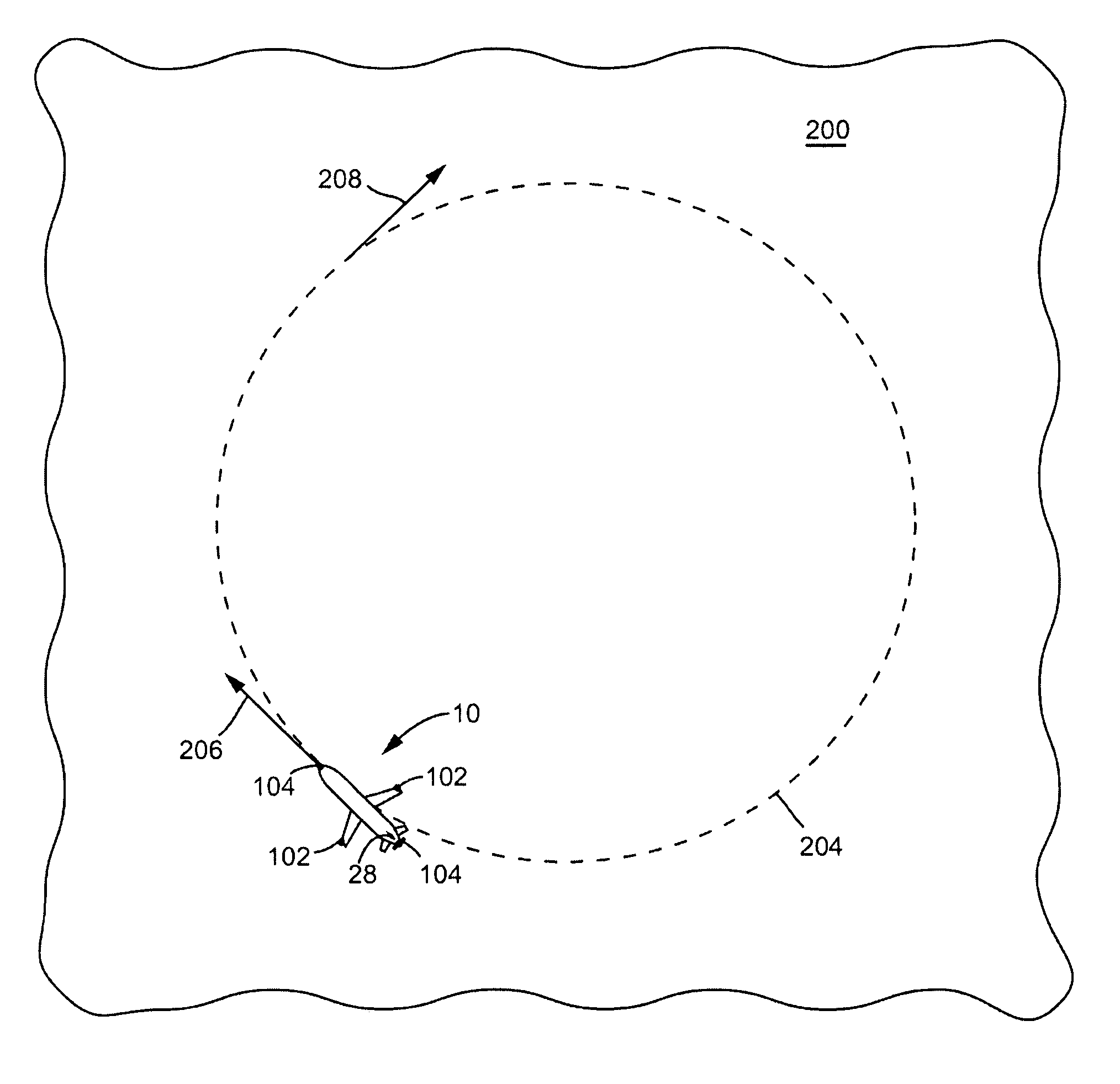
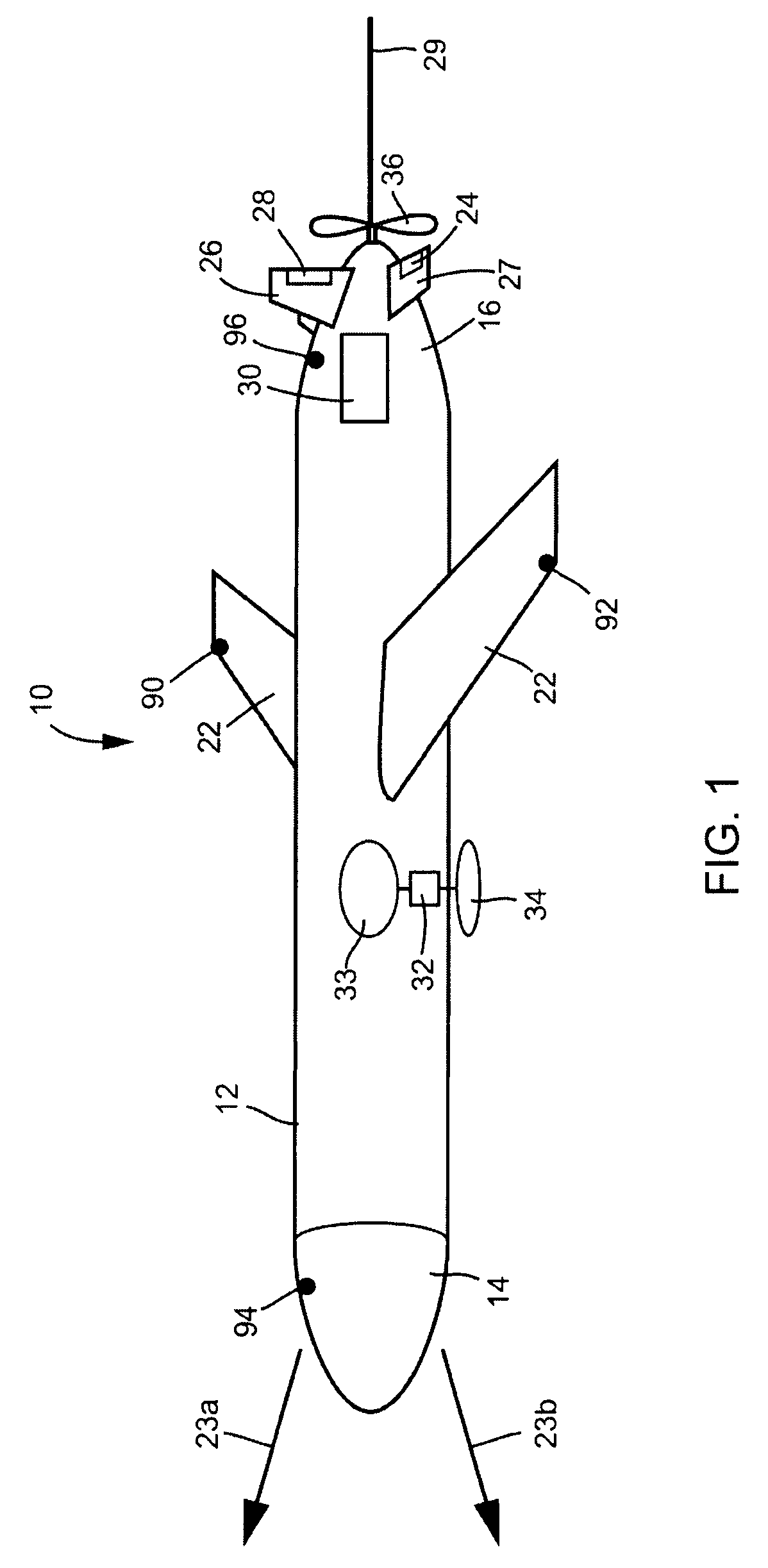
[0013]Referring to FIG. 1, an autonomous underwater vehicle (“AUV”) adapted to practice the present invention is shown in perspective view. AUV 10 is a submersible vehicle configured to operate while suspended (e.g. buoyantly suspended) in a volume of liquid, shown as ocean 200. AUV 10 has a sealed hull 12 that is generally cylindrical in shape. Hull 12 may be configured as a pressure hull having a longitudinal axis. Hull 12 generally has a front end 14 and a rear end 16, and an exterior wall defining an interior cavity. The interior cavity of hull 12 houses batteries, electronics, controllers, and buoyancy controls. The batteries, electronics, controllers, and buoyancy controls are generally distributed within hull 12 so that AUV 10 has a center of mass that is below the center of buoyancy, thereby stabilizing the AUV in a vertical orientation when suspended in ocean 200. AUV 10 may optionally be provided with two wings 22 extending generally laterally from hull 12.

[0014]Hull 12 ma...


PUM


Abstract

The present invention relates to an autonomous underwater vehicle (“AUV”) for monitoring underwater fluid currents by detecting electrical currents induced by the flow of a conductive liquid through the Earth's magnetic field. More particularly, the present invention relates to the gathering of data related to underwater fluid currents and the control of AUV motion during data gathering.

Description

CROSS-REFERENCE TO RELATED PATENT APPLICATIONS[0001]1. Field of the Invention[0002]The present invention relates to an autonomous underwater vehicle (“AUV”) having control and circuitry for monitoring underwater fluid currents. More particularly, the present invention relates to the gathering of data related to underwater fluid currents and the control of AUV motion during data gathering.[0003]2. Background of the Invention[0004]Ocean water is a conductive fluid that moves within the magnetic field of the Earth. As such, an electric current is induced in the water as a result of its movement within the magnetic field. Furthermore, the ocean water does not move uniformly, but rather, moves in linear and non-linear horizontal and vertical fluid currents. By measuring the electrical current in the ocean at a given location, and monitoring changes in this electrical current relative to time and location, the magnitude and direction of fluid currents at a given location of the ocean can ...

Claims


Application Information

Patent Timeline
Patent Type & Authority Patents(United States)
IPC IPC(8): G01V1/28G01V3/38H02G15/00
CPCB63C11/36G01C13/002G05D1/0692G06T11/206B63G8/001B63B2211/02
Inventor WEBB, DOUGLAS C.
Owner TELEDYNE INSTR INC
Why Eureka
Try Eureka