
Control circuit and method for a buck-boost power converter

a control circuit and power converter technology, applied in the direction of power conversion systems, dc-dc conversion, instruments, etc., can solve problems such as large output ripple, and achieve the effects of minimizing output ripple, minimizing transient response, and improving efficiency

Active Publication Date: 2012-09-18
RICHTEK TECH
View PDF11 Cites 23 Cited by
  • Summary
  • Abstract
  • Description
  • Claims
  • Application Information

AI Technical Summary

Benefits of technology

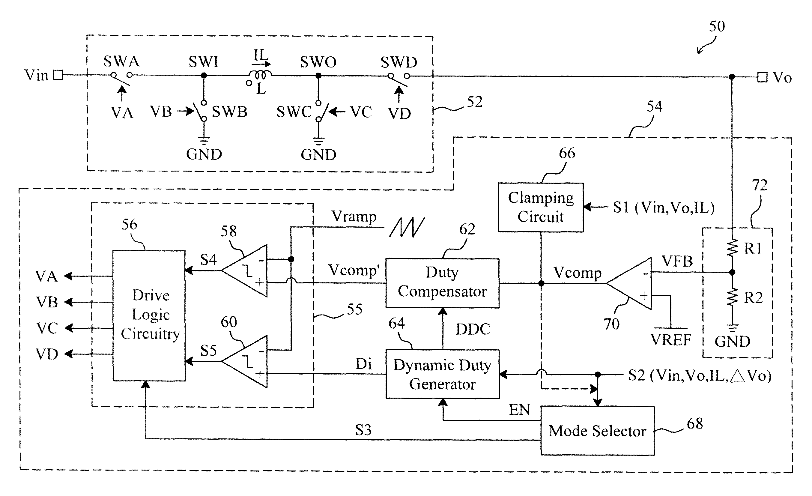
The present invention provides a control circuit and method for a buck-boost power converter that can optimize the switching sequence of power switches to improve efficiency, minimize output ripple, and reduce transient response. The control circuit includes a feedback circuit to detect the output voltage and an error amplifier to amplify the difference between the feedback signal and a reference voltage. A clamping circuit can clamp the level of the error signal based on a first detecting signal, and a duty compensator can compensate the error signal according to a compensation signal to generate a compensated error signal. A dynamic duty generator can generate a duty insertion signal based on a second detecting signal, and a mode selector can provide an enable signal to enable the dynamic duty generator. The control circuit can provide improved efficiency, minimize output ripple, and reduce transient response of the buck-boost power converter.

Problems solved by technology

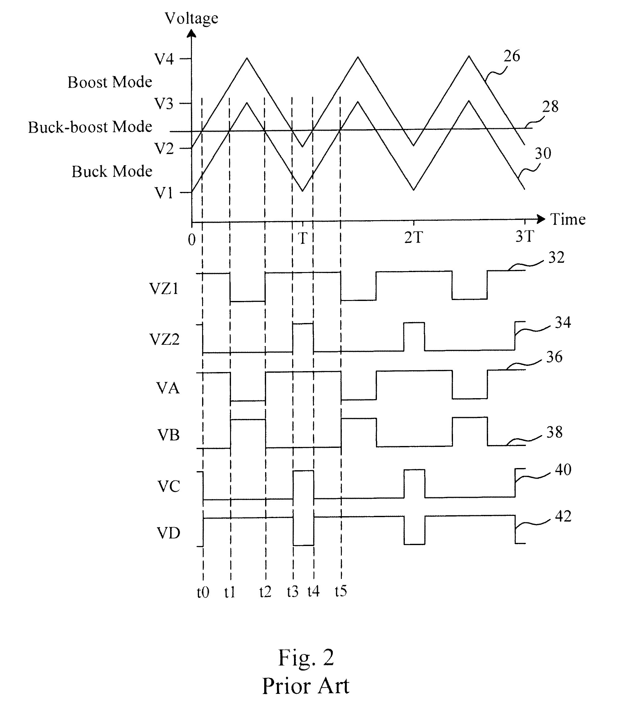
However, this fixed duty inserted method may cause a discontinuous duty during mode switching and thereby result in large output ripple.

Method used


Image

  • Control circuit and method for a buck-boost power converter
  • Control circuit and method for a buck-boost power converter
  • Control circuit and method for a buck-boost power converter

Examples


Embodiment Construction

[0030]In an embodiment according to the present invention, as shown in FIG. 3, a buck-boost power converter 50 includes a buck-boost power stage 52 and a control circuit 54 to provide control signals VA, VB, VC and VD to switch the power switches SWA, SWB, SWC and SWD connected to an inductor L in the buck-boost power stage 52 to convert an input voltage Vin to an output voltage Vo. In the control circuit 54, a feedback circuit 72 detects the output voltage Vo to generate a feedback signal VFB, an error amplifier 70 amplifies the difference between the feedback signal VFB and a reference voltage VREF to generate an error signal Vcomp, a clamping circuit 66 clamps the level of the error signal Vcomp according to a detecting signal S1 related to at least one of the input voltage Vin, output voltage Vo and inductor current IL, a mode selector 68 generates a mode switch signal S3 according to a detecting signal S2 related to at least one of the input voltage Vin, output voltage Vo, indu...


PUM


Abstract

Control signals are generated for a buck-boost power stage of a buck-boost power converter to convert an input voltage to an output voltage. The buck-boost power stage includes an inductor and at least two power switches connected thereto. The output voltage is monitored to generate an error signal having clamped level according to a first detecting signal related to at least one of the input voltage, output voltage and inductor current. In a buck-boost mode, a compensation signal and a duty insertion signal are generated according to a second detecting signal related to at least one of the input voltage, output voltage, inductor current and variation of the output voltage, the error signal is compensated with the compensation signal to generate a compensated error signal, and the control signals are determined upon the combination of the compensated error signal, the duty insertion signal and a ramp signal.

Description

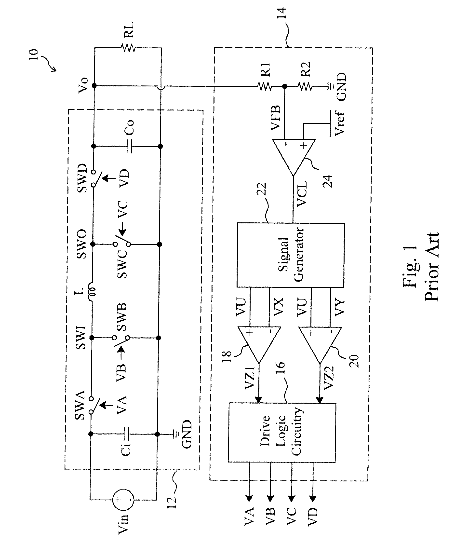
FIELD OF THE INVENTION[0001]The present invention is related generally to a buck-boost power converter and, more particularly, to a control circuit and method for a buck-boost power converter.BACKGROUND OF THE INVENTION[0002]As shown in FIG. 1, a conventional synchronous buck-boost power converter 10 includes a buck-boost power stage 12, and a control circuit 14 to provide control signals VA, VB, VC and VD t6 switch the power switches SWA, SWB, SWC and SWD in the buck-boost power stage 12, respectively, to convert an input voltage Vin to an output voltage Vo. In the control circuit 14, resistors R1 and R2 establish a voltage divider to divide the output voltage Vo to generate a feedback signal VFB, an error amplifier 24 amplifies the difference between the feedback signal VFB and a reference voltage Vref to generate an error signal VCL, a signal generator 22 provides a signal VU related to the error signal VCL and ramp signals VX and VY, a comparator 18 compares the signal VU with t...

Claims


Application Information

Patent Timeline
Patent Type & Authority Patents(United States)
IPC IPC(8): G05F1/44
CPCH02M3/1582H02M3/156
Inventor LIN, SHUI-MU
Owner RICHTEK TECH
Learn More