Blade support limb for vertical axis wind turbine

a support limb technology, which is applied in the direction of rotors, greenhouse gas reduction, vessel construction, etc., can solve the problems of low power under a low wind speed, reduce the efficiency of the vertical axis wind turbine, and schemes are not suitable for the vertical axis, so as to achieve constant power

Active Publication Date: 2012-09-25
YAN QIANG
View PDF21 Cites 15 Cited by
  • Summary
  • Abstract
  • Description
  • Claims
  • Application Information

AI Technical Summary

Benefits of technology

[0026]Through improving the blade support limb structure, this invention keeps a wind wheel at stable rotation speed under the condition that the environmental wind speed exceeds the rated wind speed, thereby to ensure that vertical axis wind turbine outputs constant power.

Problems solved by technology

However, there is a non-neglectable problem with the existing vertical axis wind turbines: as an ambient wind speed is greater than a rated wind speed, a power output of a wind rotor correspondingly increases, as the ambient wind speed is far greater than the rated wind speed, the wind rotor is incapable of operating. FIG. 1 shows the structure of the blade support limb in the prior art.
However, considering the characteristics of a motor, if the rated wind speed is high, the power will be very low under a low wind speed.
And there are mostly low wind speeds under the natural state, which thus decreases the efficiency of the vertical axis wind turbine.
However, considering the costs, such schemes are not suitable for the vertical axis wind turbine from several kilowatts to dozens of kilowatts output.

Method used


Image

  • Blade support limb for vertical axis wind turbine
  • Blade support limb for vertical axis wind turbine
  • Blade support limb for vertical axis wind turbine

Examples


example 1

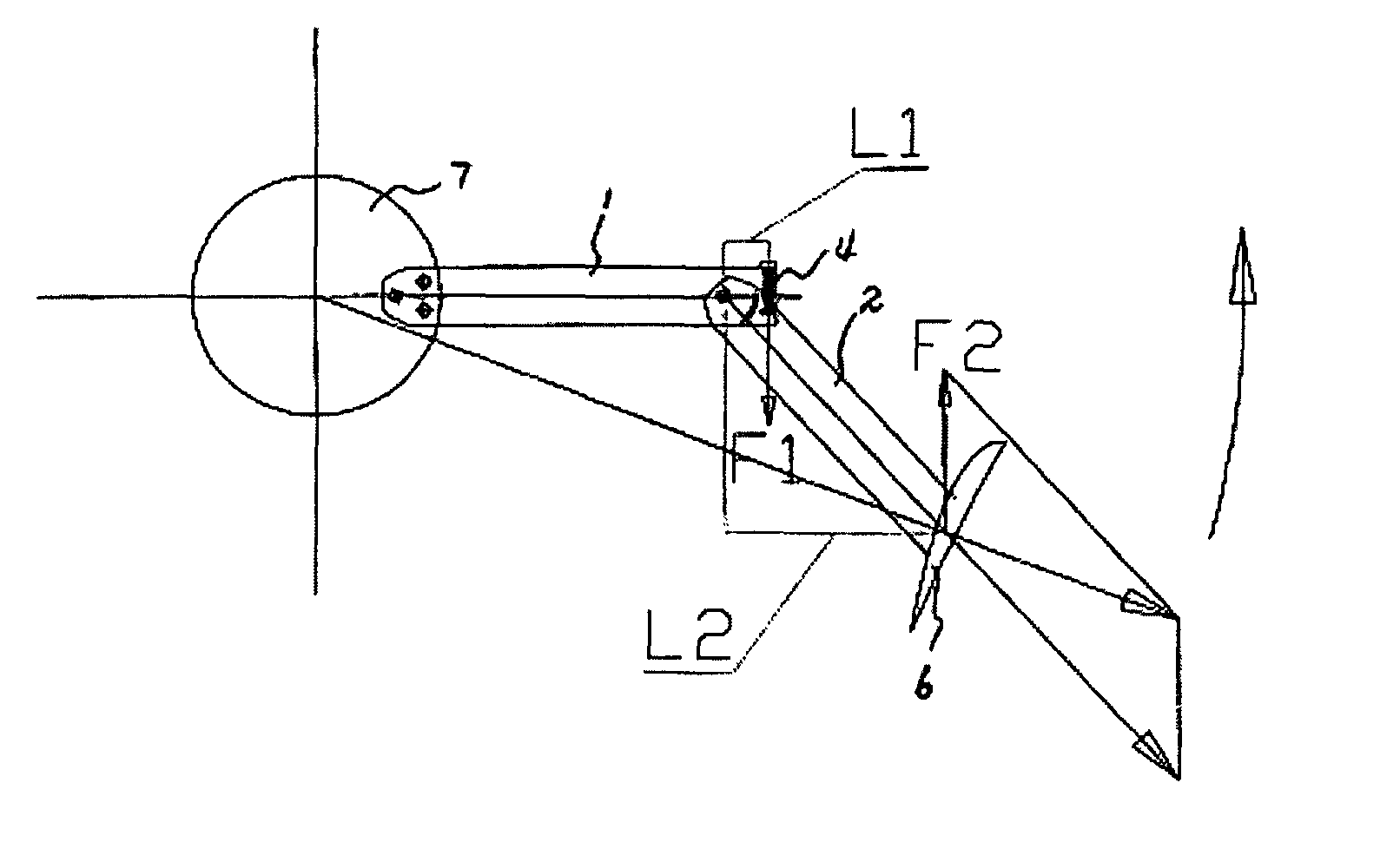
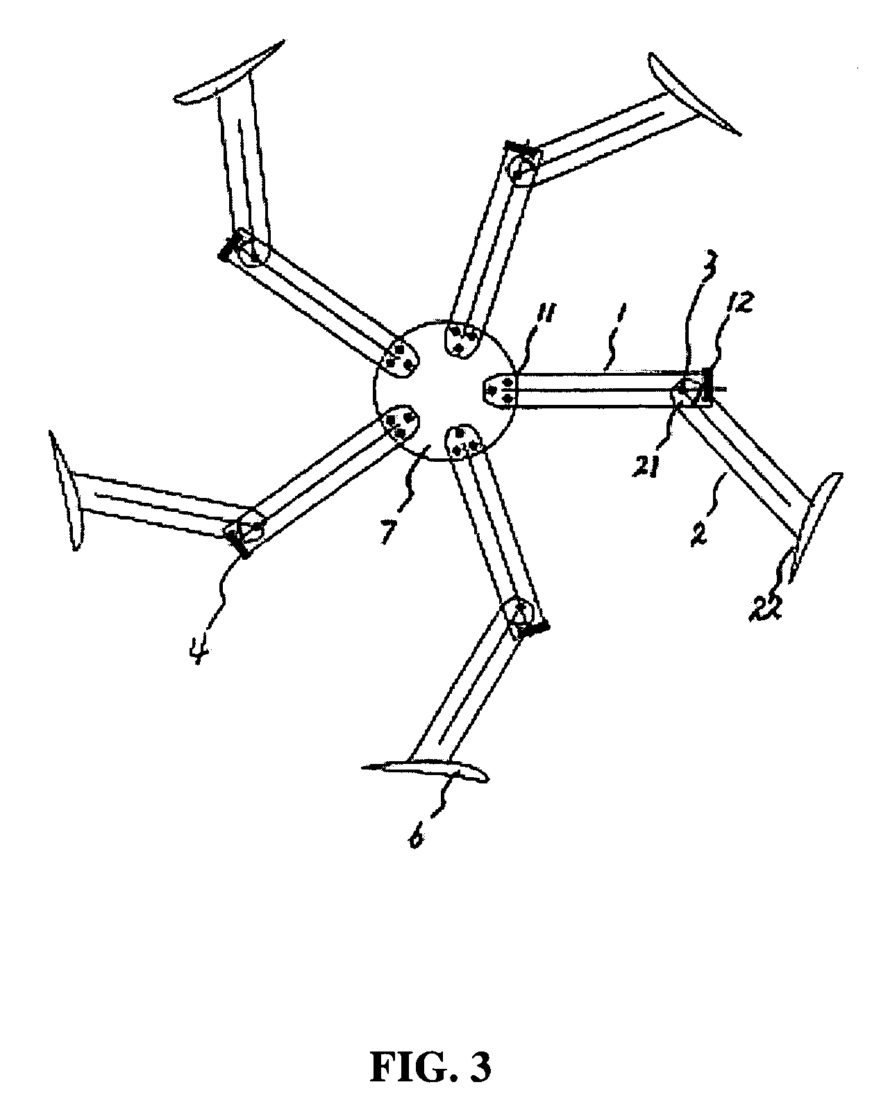
[0039]FIG. 3 shows the blade support limb structure for the vertical axis wind turbine of the present invention. The other end (11) of the fixed support limb (1) is fixed with the flange on the vertical axis. One end (21) of a rotatable support limb (2) is connected with one end (12) of the fixed support limb, and may rotate around one end (12) of the fixed support limb. The other end (22) of the rotatable support limb is fixed with the blades. There is a gyration center axis (3) at the connection of one end (21) of the rotatable support limb and one end (12) of the fixed support limb, and the rotatable support limb may rotate around it. There is a control component (4) at one end (12) of the fixed support limb, which is used to control the rotation angle (β) of the rotatable support limb (2) around the gyration center axis (3). Both ends (41) (42) of the control component are respectively connected to one end (21) of the rotatable support limb and one end (12) of the fixed support ...

example 2

[0042]For the blade support limb structure in Example 1, it is set as the prerequisite that the wind rotor with the diameter 1.36 m consists of blades of Goe63 airfoil, the length ratio of fixed support limb to rotatable support limb is 1:1, and the rated wind speed is 10 m / s, i.e., the wind speed of such device begins to affect the vertical axis wind turbine from 10 m / s. Through CFD, when the wind speed increases from 10 m / s to 15 m / s, 20 m / s and 25 m / s, the output power increases respectively from 170 watts to 210 watts, 220 watts and 230 watts. But the output power will increase from 170 watts to about 2660 watts without the blade support limb structure in this invention.

[0043]

CFD calculation tablewind speed10 m / s15 m / s20 m / s25 m / sPower output by using existing17035013602660blade support limb structure (watt)Power output by using the blade170210225230support limb structure in thisinvention (watt)

example 3

[0044]Also for the blade support limb structure in Example 1, wind tunnel tests are performed by means of the same wind rotor and parameters. It is set as the prerequisite that the length ratio of fixed support limb to rotatable support limb is 1:1, when the wind speed increases from 10 m / s to 15 m / s, 20 m / s and 25 m / s, the output power of the motor increases respectively from 158 watts to 193 watts, 198 watts and 202 watts. But the output power of the motor will reach about 2600 watts without such device.

[0045]

Table of wind tunnel testswind speed10 m / s15 m / s20 m / s25 m / sPower output by using16057013202600existing blade supportlimb structure (watt)Power output by using158193198202the blade support limbstructure in thisinvention (watt)


PUM


Abstract

A blade support limb structure of a vertical axis wind power generator includes a fixed support limb (1) and a rotatable support limb (2), one end (21) of the rotatable support limb is connected with one end (22) of the fixed support limb and the rotatable support limb may rotate around it. The structure keeps a wind wheel at stable rotation speed in the case the environmental wind speed exceeds the rated wind speed, thereby to ensure that vertical axis wind power generator outputs constant power. The structure solves a problem of constant power output of the vertical axis wind power generator from hundreds watts to thousands watts, so its applications are wide.

Description

CROSS-REFERENCE TO RELATED APPLICATIONS[0001]This application is a continuation of International Patent Application No. PCT / CN2007 / 001984 with an international filing date of Jun. 25, 2007, designating the United States, now pending, and further claims priority benefits of Chinese Patent Application No. 200610117017.0 filed Oct. 11, 2006. The contents of all the aforementioned specifications, including any intervening amendments thereto, are incorporated herein by reference.BACKGROUND OF THE INVENTION[0002]1. Field of the Invention[0003]This invention relates to a blade support limb, and particularly to a blade support limb for a vertical axis wind turbine.[0004]2. Description of the Related Art[0005]Vertical axis wind turbines are widely used for generating power and each comprises a wind rotor. However, there is a non-neglectable problem with the existing vertical axis wind turbines: as an ambient wind speed is greater than a rated wind speed, a power output of a wind rotor corres...

Claims


Application Information

Patent Timeline
Patent Type & Authority Patents(United States)
IPC IPC(8): F03D7/06
CPCF03D3/061F03D7/06Y02E10/74F05B2240/202F03D3/06
Inventor YAN, QIANG
Owner YAN QIANG
Why Eureka
Try Eureka