Composite collector bar

a collector bar and composite technology, applied in the field of electrolytic reduction cells, can solve problems such as significant increase in consumption, and achieve the effect of minimising heat loss and optimising electrical current distribution

Inactive Publication Date: 2012-09-25
BHP BILLITON INNOVATION PTY LTD
View PDF14 Cites 0 Cited by
  • Summary
  • Abstract
  • Description
  • Claims
  • Application Information

AI Technical Summary

Benefits of technology

[0020]The first conductor of the composite collector bar is preferably produced from material which is of relatively low thermal and electrical conductivity, such as steel. The low thermal conductivity reduces heat loss through the ends of the collector bar, and particularly to the external current carrier arrangement.
[0021]In contrast to the first conductor, the second conductor of the composite collector bar is preferably produced from a material of relatively high thermal and electrical conductivity, such as copper. Thus the second conductor is of higher thermal and / or electrical conductivity compared to the first conductor. The higher electrical conductivity of the second conductor provides an approximately uniform electrical potential through the collector bar, thereby promoting a uniform current density at the surface of the cathode block. Additionally, the higher electrical conductivity of the second conductor provides a path of lower resistance between the cathode blocks and the external current carrier, thereby reducing the voltage drop through the cathode block assembly.
[0024]The relative cross-sectional areas of the first and second conductors of the composite collector bar are designed to optimize electrical currents and heat flux through the composite. Although the ratio of the areas of the first and second conductors of the collector bar are dependent upon details of the cathode and refractories design, for reasons of cost, the cross-sectional area of the second (highly conductive) conductor of the composite will preferably comprise less than 50% of the total collector bar cross-section. Mathematical modelling may be used to optimally position the two conductors of the composite collector bar against the cathode block to minimise heat loss and optimise the electrical current distribution across the outer face of the cathode block.
[0025]As a further elaboration of this invention, the relative cross-sectional areas of the first and second conductors of the collector bar can be varied in subsequent cathode blocks in the cathode along the length of the electrolytic cell. Variation in the relative cross-sectional areas of the collector bar conductors between subsequent cathode block assemblies may be used to beneficially alter the distribution of the current density field and total current flow through the cell.

Problems solved by technology

This uneven distribution of current has the deleterious effect of significantly increasing the consumption (generally by means of erosive processes) of the cathode blocks in the areas of highest current concentration.

Method used


Image

  • Composite collector bar
  • Composite collector bar
  • Composite collector bar

Examples


Embodiment Construction

[0031]A preferred embodiment of the invention will now be described with reference to the above drawings.

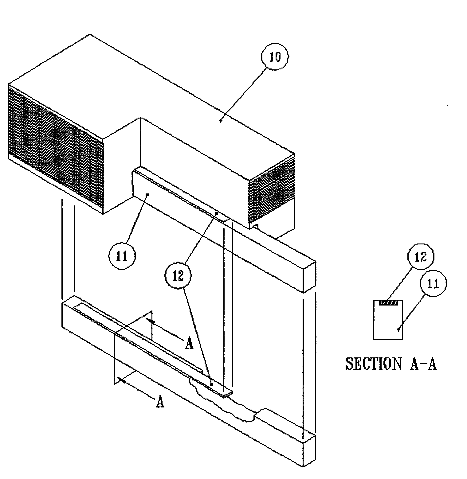
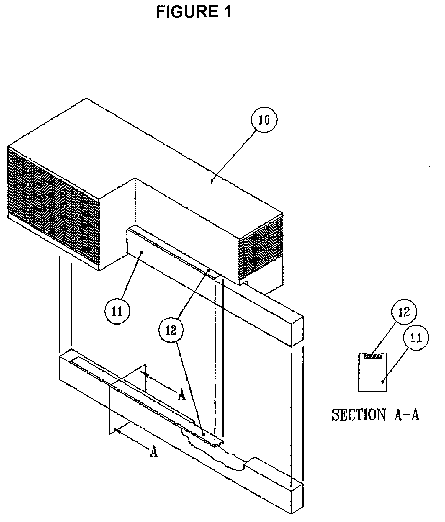
[0032]Referring to FIG. 1, a collector bar according to an embodiment of the invention is shown. A cathode block 10 is shown having a collector bar fitted within a recess formed in the cathode block 10. The collector bar includes a first conductor 11 which is typically a steel body and a second conductor 12 which is typically formed from a highly conductive metal such as copper fitted into a recess within the first conductor 11. In this embodiment of the invention that portion of the collector bar which houses the conductive insert is located entirely within the cathode block. Cross section A-A (FIG. 1) of the collector bar shows that the second conductor 12 is much thinner than the first conductor 11. The second conductor 12 is located within the upper external surface of first conductor 11 such that the external surface incorporating the second conductor is exposed to the catho...


PUM

PropertyMeasurementUnit
temperatureaaaaaaaaaa
electrically-conductingaaaaaaaaaa
electrical resistanceaaaaaaaaaa

Abstract

A collector bar for electrical connection to a busbar system of an electrolytic cell, the collector bar being received within a recess in a cathode block of the cathode of the electrolytic cell; wherein the collector bar comprises a first conductor which electrically connects to the busbar system, the first conductor having an external surface or surfaces which electrically contact the cathode block and at least one second conductor having a lower electrical resistance to the first conductor, the second conductor being positioned on at least one external surface of the first conductor in electrical contact with the first conductor.

Description

FIELD OF THE INVENTION[0001]The present invention relates to the electrolytic reduction cells used for the production of aluminium and in particular the collector bars forming part thereof.BACKGROUND OF THE INVENTION[0002]Aluminium metal is generally extracted from alumina (Al2O3) electrolytically by a method commonly referred to as the Hall Héroult process. This process is well known to practitioners in the aluminium industry, and needs no further discussion here.[0003]Rather than directing attention to the process itself, the focus of this invention lies on the vessel or cell in which this electrolytic process is operated. The upper (anodic) portion of the cell is typically comprised of one or more current carrying (commonly carbonaceous) blocks intended to evenly distribute electrical current across a shallow (in the sense that it is of much greater dimension horizontally than vertically through its depth) liquid layer of molten cryolite, surmounting another layer of molten alumi...

Claims


Application Information

Patent Timeline
Patent Type & Authority Patents(United States)
IPC IPC(8): C25C3/08C25C3/16
CPCC25C3/16
Inventor BAYER, INGOOLMSTEAD, BRUCE RINGSBY
Owner BHP BILLITON INNOVATION PTY LTD
Why Eureka
Try Eureka