
Microdispenser and associated operating method

a technology of micro-dispensers and operating methods, which is applied in the direction of positive displacement liquid engines, laboratory glasswares, instruments, etc., can solve the problems of occupying a large amount of time for filling via nozzles and subsequent closing of nozzles, and no time-intensive rinsing operations are carried ou

Active Publication Date: 2012-09-25
SCIENION GMBH
View PDF46 Cites 14 Cited by
  • Summary
  • Abstract
  • Description
  • Claims
  • Application Information

AI Technical Summary

Benefits of technology

[0018]In one variant of the invention, the microdispenser is configured for single use, wherein the sample container (e.g. a glass capillary) is not refillable. In this variant, the single-use microdispenser is filled with the desired sample liquid at the factory and then stored and delivered, i.e. transported to the customer, in the filled state, wherein no sample liquid can escape from the microdispenser. In this way, contamination of the sample liquid located in the microdispenser is completely prevented, since the sample liquid is enclosed in the microdispenser in a sterile manner. Preferably, the sample container is therefore fully closed apart from the nozzle and, apart from the nozzle which is closed during storage or transport, has no other opening through which sample liquid could escape during storage or transport.
[0019]On the other hand, in another variant of the invention, the microdispenser has a valve for venting the sample container during the dispensing operation and / or for filling the sample container, which allows reuse of the microdispenser according to the invention. The microdispenser can, e.g., be filled with the desired sample liquid through the valve at the factory, and then the valve is closed during storage and transport. For the actual dispensing operation, the valve is then opened in order to vent the sample container, so that the dispensing of the sample is not prevented due to the build-up of an excess vacuum within the sample container. The valve in this case is preferably structurally integrated in the microdispenser and forms a unit with the microdispenser, whereby the dispenser according to the invention differs from the known microdispensers described above in which a supply line is connected to a separate pressure control device.
[0031]Preferably, the actuator surrounds the sample container in the manner of a sleeve, as known per se from the prior art. Here, the sleeve-like actuator can be pushed onto the sample container, wherein the actuator can be fixed in the pushed-on state by means of a mounting sleeve. The mounting sleeve may for example be fixed on the sample container by screwing or by means of a securing ring. It is also advantageous if the mounting sleeve has a spring slot which runs in the axial direction, so that the mounting sleeve can expand slightly in the radial direction.
[0033]It is also advantageous if the nozzle and / or the sample container is provided with a coating which permits specific adsorption of biomolecules, prevents coagulation of a sample contained in the microdispenser and / or is suitable for purifying and / or concentrating the sample. Suitable substances for such coatings are known per se from standard methods of biotechnology and biochemistry.
[0035]Furthermore, the sample container preferably has both a sample reservoir and a working chamber. The working chamber in this case serves to discharge an individual sample from the microdispenser. To this end, the working chamber can be compressed radially and / or longitudinally for example by means of a piezo actuator, as known per se. The sample reservoir, on the other hand, serves to hold a sufficient quantity of sample to make it possible to dispense a number of samples one after the other without having to refill the microdispenser in a manner that may lead to contamination. The sample reservoir therefore preferably has a larger volume than the working chamber of the sample container.
[0037]Furthermore, it is also possible within the scope of the invention that the sample reservoir permits a change in volume on account of the design or the material used. The sample reservoir may for example have a flexible and preferably elastic wall, so that the volume of the sample reservoir can be reduced by compressing the sample container in the region of the sample reservoir.

Problems solved by technology

Furthermore, no time-intensive rinsing operations are carried out.
By contrast, in the other known microdispensers in which filling takes place from the front via the nozzle, the filling via the nozzles and the subsequent closing of the nozzles would take up a large amount of time.

Method used


Image

  • Microdispenser and associated operating method
  • Microdispenser and associated operating method
  • Microdispenser and associated operating method

Examples


Embodiment Construction

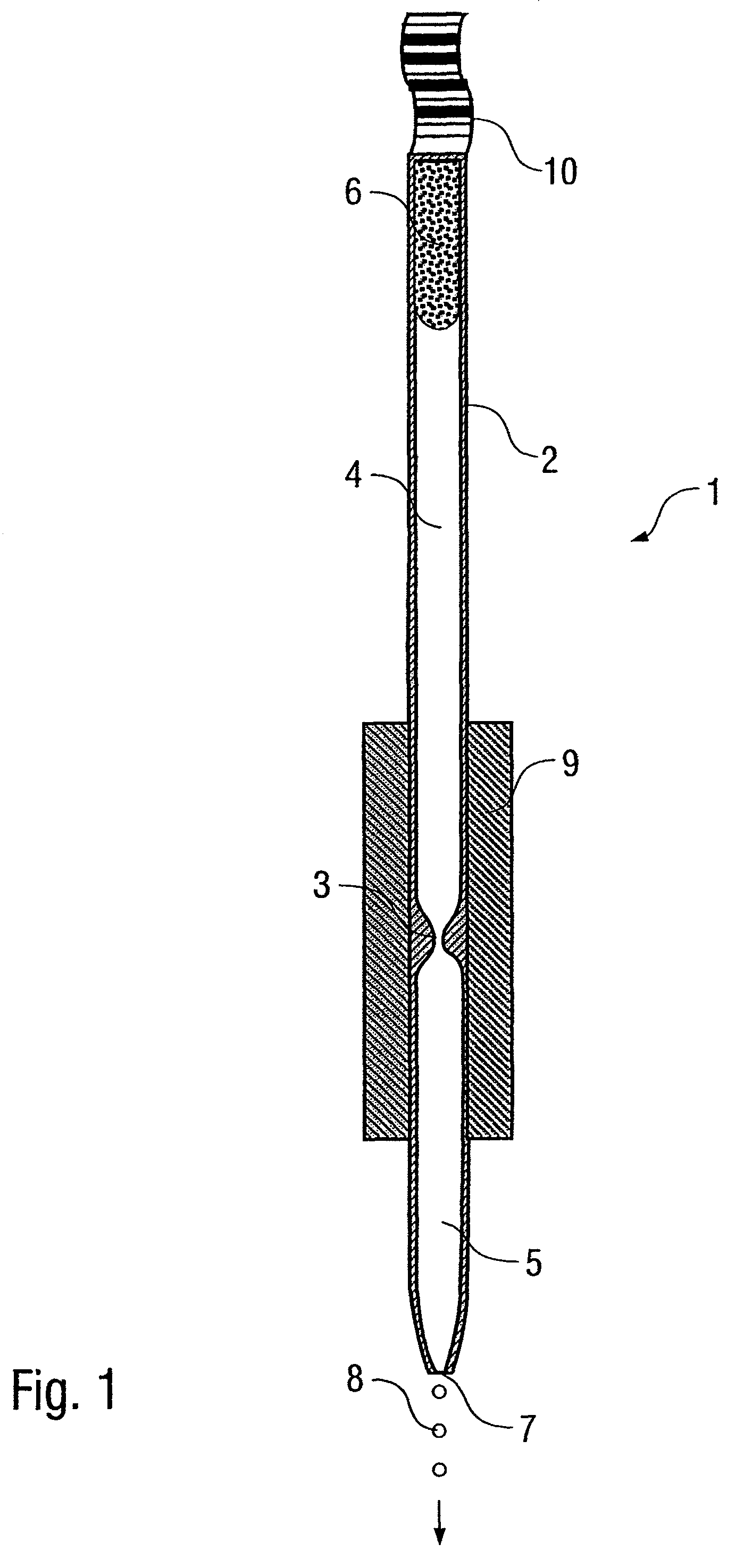
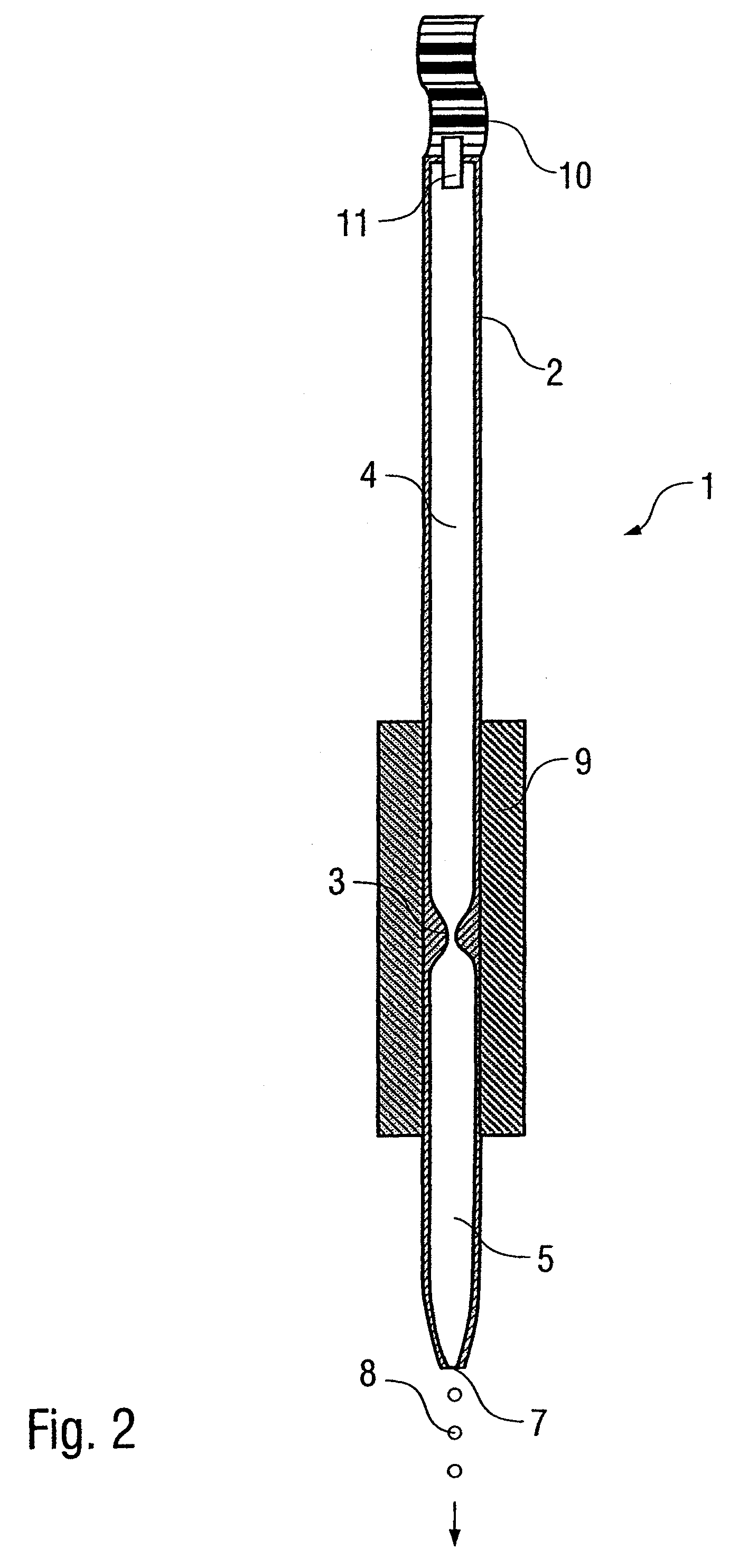
[0057]The cross-sectional view in FIG. 1 shows a microdispenser 1 according to the invention which can be used in a dispensing device (not shown) to dispense microdroplets.

[0058]In order to hold a sample liquid, the microdispenser 1 has a sample container 2 in the form of a glass capillary with a volume of 20 μl, wherein the sample container 1 has a narrowing 3 which divides the sample container 2 into a sample reservoir 4 and a working chamber 5.

[0059]Arranged in the sample reservoir 4 is a sponge 6 which exerts on the sample liquid capillary forces which generate a holding vacuum in the sample reservoir 4, as a result of which the sample liquid is prevented from running out of the sample container 2.

[0060]Furthermore, the sample container 2 has a nozzle 7 with a nozzle diameter of 70 μm, through which microdroplets 8 can be dispensed.

[0061]The dispensing of the microdroplets 8 is brought about by a piezo actuator 9 which surrounds the sample container 2 in the manner of a sleeve i...


PUM


Abstract

The invention relates to a microdispenser (1) for dispensing a liquid sample in a dispensing device, with a sample container (2) for receiving the liquid sample, and with a nozzle (7) for dispensing the sample located in the sample container (2). The microdispenser (1) with the filled sample container (2) can in this case be stored independently of and fluidically separately from the dispensing device, without the sample escaping from the sample container (2) during storage.

Description

BACKGROUND OF THE INVENTION[0001]The invention relates to a microdispenser for dispensing a liquid sample in a dispensing device and also to an associated operating method.[0002]Microdispensers are known for example from WO 99 / 30168 and are used inter alia for biological or chemical purposes in order to dispense small volumes of liquid in a controlled manner in the form of microdroplets. One example of this is the production of miniaturized DNA arrays for genetic engineering uses, wherein a high clone density is achieved by means of a small droplet size, for which piezoelectrically operated microdispensers are particularly suitable. The known microdispensers consist of a glass capillary for holding the sample liquid to be dispensed, the glass capillary having a nozzle for dispensing the microdroplets and a flexible supply line for filling it with the sample liquid. The discharging of the microdroplets from the glass capillary in the known microdispensers is brought about by means of...

Claims


Application Information

Patent Timeline
Patent Type & Authority Patents(United States)
IPC IPC(8): B01L3/02B67D7/36B01L99/00
CPCG01N35/10G01N2035/1039
Inventor EICKHOFF, HOLGERWURZEL, CHRISTIAN
Owner SCIENION GMBH
Learn More